Home » Design
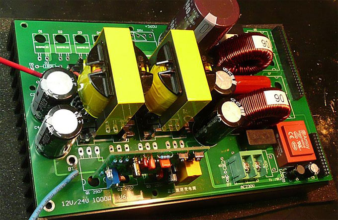
This is a full set of 12V/1500W power inverter. This is a single-sided PCB with straight pin elements. Because now is very hard to get so many specifications of the element, since a 0805 resistor is 5K, buy a hardly used up, so I installed straight pin elements. And for a lot of people, they can do on their own with a thermal transfer with the one-side PCB.
The main change of the 1500 watt power inverter is the 12V input, I used the full input and output full isolation design, so a total of three transformer windings.The following is a tube IRF1404 three pairs of work as part of the boost. I will be separated from the radiator to the best way of heat conduction heat treatment. My power supply is 12V 130A, the output AC power to 1100W when the radiator lukewarm, the fan is not used at the time.
The main change of the 1500 watt power inverter is the 12V input, I used the full input and output full isolation design, so a total of three transformer windings.The following is a tube IRF1404 three pairs of work as part of the boost. I will be separated from the radiator to the best way of heat conduction heat treatment. My power supply is 12V 130A, the output AC power to 1100W when the radiator lukewarm, the fan is not used at the time.
All in all, says this is a 24V pure sine wave inverter, this power inverter is composed of three parts: 1. Front-driver board; 2. Stage drive plate; 3. Power board.
Pre-driver board is mainly made up of three small parts, an auxiliary power supply section, a part of the PWM drive, and the third part is the protection portion;
After the class driver board consists of three parts, one is to generate SPWM signals (MCU to complete) section, a hardware RC dead time setting section; then one is driving portion of the IR2110.
Along with the wider application of PWM technology used in inverting and the inverse frequency fields, as well as the rapid development of IGBT, MOSFET and other power switching device of such PWM control of high-voltage power supply toward miniaturization, high frequency, intelligent, high efficiency direction.
With the development of power electronics technology, power inverter application has penetrated into all areas, generally require a high quality for inverter output waveform. Power inverter output waveform quality includes two aspects, namely, steady-state accuracy and dynamic performance. Therefore, the study has both structure and simple control, but also has excellent dynamic and static performance inverter control program, has been a hot topic of research in the field of power electronics.
This is a kind of excellent performance power inverter for home circuit diagram, materials are easy to get, and the output power can reach 150W. This circuit is envisaged frequency in 300Hz. The purpose is to reduce the inverter transformer size and weight, output is square wave. The inverter can be used in home lighting, electronic ballasts for fluorescent lamps, and household appliances for switching power supply when the power fails. It is simple to make this power inverter for us.

12v 300w uni-polar isolation of pure sine wave inverter Basic parameters
Nominal power: 300W; continuous power: 250W; Peak power: 600W;
Output voltage: Output single phase 220VAC (RMS), a frequency of 50±1Hz.
Overall efficiency: 87%; 300 times the power short-circuit, short-circuit power 200 times;
Overload protection 500W; immediate short circuit protection; voltage alarm 10.3V delay 1.5S;
Under-voltage protection 10V immediate shutdown; over-voltage protection 15V immediate shutdown; overheat protection: 65℃.
Many home power inverter circuit is simple and easy, but the efficiency is not high; some power inverters are in high quality and efficiency, but not easy to be made. This article describes the power inverter circuit is simple, low cost, easy maintenance, high efficiency, and is easy to be made. Although it does not have the high-end commercial complex of high-quality home inverter switching power supply integrated circuit, but the effect is not inferior.
Here's a 500W single silicon high-frequency power inverter. Its main functions and features are:
1. Reverse power protection applied switching tube to do anti-reverse protection;
2. The fan applied delay shut off to ensure effective cooling of the device;
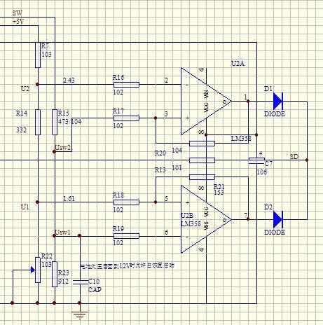
3. Applied LM358 for pre-amp over-current (short circuit) protection;
4. When the device temperature exceeds 75 degree, the machine will automatically shut down by normally closed temperature control switch. This will prevent damage of overheating;
5. Power-amp over-current and short circuit protection applied lock protection using current transformer isolated. After protection motion, we need to press the switch again to restart the device;
6. Including 5 seconds shut down function (to protect personal safety, duration adjustable);
7. Single silicon/mixer, dual adjustment;
8. Mature circuit, reasonable circuit designing, good consistency, Component neatly symmetrical, elegant appearance.
1. Reverse power protection applied switching tube to do anti-reverse protection;
2. The fan applied delay shut off to ensure effective cooling of the device;
3. Applied LM358 for pre-amp over-current (short circuit) protection;
4. When the device temperature exceeds 75 degree, the machine will automatically shut down by normally closed temperature control switch. This will prevent damage of overheating;
5. Power-amp over-current and short circuit protection applied lock protection using current transformer isolated. After protection motion, we need to press the switch again to restart the device;
6. Including 5 seconds shut down function (to protect personal safety, duration adjustable);
7. Single silicon/mixer, dual adjustment;
8. Mature circuit, reasonable circuit designing, good consistency, Component neatly symmetrical, elegant appearance.
I spent nearly a month design a 600w pure sine wave power inverter. The machine has the following characteristics:
1. SPWM drive core uses a single SPWM chip, TDS2285. So compared with pure hardware terms, SPWM driving portion is relatively simple. Things need to be debugged is fewer after finished.
2. Use single panel for all PCB to facilitate your production. Because a lot of fans can make their own one-sided PCB, some use photographic method, some use thermal transfer method, etc. Thus, users do not need to bother PCB manufacturers, and they can do it at home.
3. There are many things to do manually, and you can enjoy the fun of DIY.
4. The power is only 600W. In general, lower power will offer easier successful, can do both experiments there is a certain practicality.
This power inverter is designed for 12v DC, but also can be connected to 24v DC, my goal is 800 watt, strive to 1000 watt pure sine wave output. The home inverter overall structure is, downside is a large cooling plate, upside is a power board with same size as the cooling plate, length 228mm, width 140mm. 4 power tubes of voltage boost portion, 4 power tubes of H-bridge and 4 TO220 packed fast diodes are screwed on the cooling plate directly; DC-DC voltage boost circuit driver board and SPWM driver board are plugged on the power motherboard.

Power Inverter Source
Featured Articles
How to Choose a Suitable Power ...
 How to select the inverter for an air conditioner, television, computer or the motor? How to match the battery? How long is the ...
How to select the inverter for an air conditioner, television, computer or the motor? How to match the battery? How long is the ...12V 300W Uni-polar Isolation Pure Sine ...
 12v 300w uni-polar isolation of pure sine wave inverter Basic parameters Nominal power: 300W; continuous power: 250W; Peak power: ...
12v 300w uni-polar isolation of pure sine wave inverter Basic parameters Nominal power: 300W; continuous power: 250W; Peak power: ...600w Pure Sine Wave Power Inverter ...
 I spent nearly a month design a 600w pure sine wave power inverter. The machine has the following characteristics: 1. SPWM drive ...
I spent nearly a month design a 600w pure sine wave power inverter. The machine has the following characteristics: 1. SPWM drive ...1000w 12V DC Home Power Inverter ...
This power inverter is designed for 12v DC, but also can be connected to 24v DC, my goal is 800 watt, strive to 1000 watt pure ...
This power inverter is designed for 12v DC, but also can be connected to 24v DC, my goal is 800 watt, strive to 1000 watt pure ...