Power Inverter - Homemade Cost-effective Inverter
Many home power inverter circuit is simple and easy, but the efficiency is not high; some power inverters are in high quality and efficiency, but not easy to be made. This article describes the power inverter circuit is simple, low cost, easy maintenance, high efficiency, and is easy to be made. Although it does not have the high-end commercial complex of high-quality home inverter switching power supply integrated circuit, but the effect is not inferior.
This power inverter is subject to sine wave output, no-load current is less than 450mA, load capacity of more than 300W, the efficiency of more than 85%. Usually to fans, light bulbs, electric iron supply, 100W bulb on a string or tape 29 inches below the TV are more than enough (due to degaussing coils, starting current is too large, so to start the string bulb, unplug if degaussing coil, series bulbs can’t), to life and maintenance bring great convenience. When a fault occurs, it will not cause the voltage increases, burned electrical appliances.
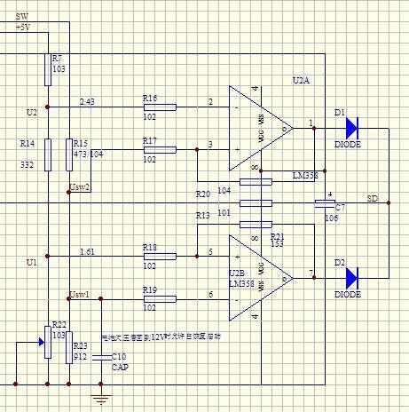
I use the power inverter for more than a year, and there have not seen any problems, the circuit as shown in the drawings.

Working principle:
After switching 12V power of the inverter multivibrator V1, V2, R1-R4, C1, C2 formed was electric start-up, V1, V2 collector output turns positive polarity close 50Hz square wave. Integrating circuit integral shaping after C3 and R5, C4 and R6 form prevail sine wave, then by V3, V4 respectively after excitation inverted amplifying V5, V6, so that the final stage power tube V7, V8 alternately turned on and off, their the collector current flowing through the transformer primary winding L1, L2 in the high-voltage side of the transformer induced approximately 50Hz quasi-sine wave voltage output.
Component selection:
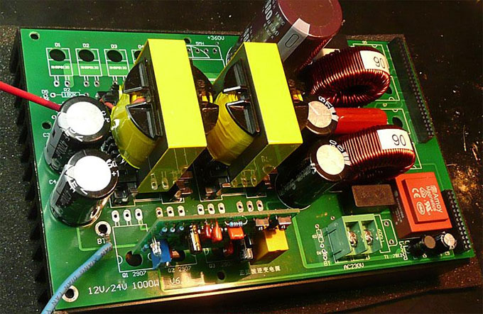
Most of the components of the power inverter can be removed from waste printed circuit board. V5, V6 with D880 or C2073. V7, V8, respectively, with three 3DD207 parallel connection, the parameters of 200V/5A/50W, can also be used 3DDl5D instead. Adjustable resistor RP can be removed from the old TV with a tail board. No specific requirements remaining resistors and capacitors. Coil Ll, L2 of the 1.62mm enameled wire, each about 50 turns. L3, L4, L5 are used Φ0.53mm enameled wire, the turns were 12, 12, 945. Power tube coupled with the greatest possible heat sink on the line, the machine is equipped with a 150cm wide fin. Transformer core is made effective cross-sectional area of 20cm2 or more, can be sufficiently large toroidal power transformer core of the core of waste battery charger or amplifier on, I use the toroidal transformer core.
Testing:
After all of the power MOSFET is mounted on a heat sink, the remaining elements welded to the power tube scaffolding with all welding methods without making circuit boards. Since the V1, V2 and element composition of the oscillation circuit due to differences in characteristics caused by V1, V2 collector output signal amplitude oscillation is inconsistent, resulting Depletion too large, so use an adjustable resistor RP to adjust the balance of the oscillation circuit. Regulator circuit consists of VD, R7 composition is to ensure stable operation of the oscillation circuit essential items, solve due to the battery voltage drop caused by the oscillation circuit imbalances. When debugging test machine, the first RW adjusted to the middle position, the 12V supply terminal string ammeter, load the power of the inverter, adjust RP, a current minimum, then the load termination on 60W bulbs; energized tune RP, a current minimum, repeat load regulation load times, no longer able to adjust this time until the current transformer close to listen, noise should be minimal. If there is no balance transfer, noisy, not close to the ear can hear the noise. V5, V6 emitter respectively through winding L3, L4 and V7, V8 inverter connected to the base, to deepen V7, V8 saturation and depth of cut. Help improve V7, V8 efficiency. Note, L3, L4 phase to correct such wrong, although there will be a high-pressure side, but the output voltage is not high, with a load capacity will be poor. After commissioning you can find a used computer power supply box. Wherein the machine is loaded, it can take advantage of the cooling fan.
This power inverter is subject to sine wave output, no-load current is less than 450mA, load capacity of more than 300W, the efficiency of more than 85%. Usually to fans, light bulbs, electric iron supply, 100W bulb on a string or tape 29 inches below the TV are more than enough (due to degaussing coils, starting current is too large, so to start the string bulb, unplug if degaussing coil, series bulbs can’t), to life and maintenance bring great convenience. When a fault occurs, it will not cause the voltage increases, burned electrical appliances.
I use the power inverter for more than a year, and there have not seen any problems, the circuit as shown in the drawings.
Working principle:
After switching 12V power of the inverter multivibrator V1, V2, R1-R4, C1, C2 formed was electric start-up, V1, V2 collector output turns positive polarity close 50Hz square wave. Integrating circuit integral shaping after C3 and R5, C4 and R6 form prevail sine wave, then by V3, V4 respectively after excitation inverted amplifying V5, V6, so that the final stage power tube V7, V8 alternately turned on and off, their the collector current flowing through the transformer primary winding L1, L2 in the high-voltage side of the transformer induced approximately 50Hz quasi-sine wave voltage output.
Component selection:
Most of the components of the power inverter can be removed from waste printed circuit board. V5, V6 with D880 or C2073. V7, V8, respectively, with three 3DD207 parallel connection, the parameters of 200V/5A/50W, can also be used 3DDl5D instead. Adjustable resistor RP can be removed from the old TV with a tail board. No specific requirements remaining resistors and capacitors. Coil Ll, L2 of the 1.62mm enameled wire, each about 50 turns. L3, L4, L5 are used Φ0.53mm enameled wire, the turns were 12, 12, 945. Power tube coupled with the greatest possible heat sink on the line, the machine is equipped with a 150cm wide fin. Transformer core is made effective cross-sectional area of 20cm2 or more, can be sufficiently large toroidal power transformer core of the core of waste battery charger or amplifier on, I use the toroidal transformer core.
Testing:
After all of the power MOSFET is mounted on a heat sink, the remaining elements welded to the power tube scaffolding with all welding methods without making circuit boards. Since the V1, V2 and element composition of the oscillation circuit due to differences in characteristics caused by V1, V2 collector output signal amplitude oscillation is inconsistent, resulting Depletion too large, so use an adjustable resistor RP to adjust the balance of the oscillation circuit. Regulator circuit consists of VD, R7 composition is to ensure stable operation of the oscillation circuit essential items, solve due to the battery voltage drop caused by the oscillation circuit imbalances. When debugging test machine, the first RW adjusted to the middle position, the 12V supply terminal string ammeter, load the power of the inverter, adjust RP, a current minimum, then the load termination on 60W bulbs; energized tune RP, a current minimum, repeat load regulation load times, no longer able to adjust this time until the current transformer close to listen, noise should be minimal. If there is no balance transfer, noisy, not close to the ear can hear the noise. V5, V6 emitter respectively through winding L3, L4 and V7, V8 inverter connected to the base, to deepen V7, V8 saturation and depth of cut. Help improve V7, V8 efficiency. Note, L3, L4 phase to correct such wrong, although there will be a high-pressure side, but the output voltage is not high, with a load capacity will be poor. After commissioning you can find a used computer power supply box. Wherein the machine is loaded, it can take advantage of the cooling fan.
Post a Comment:
You may also like:

Power Inverter Source
Featured Articles
How to Choose a Suitable Power ...
 How to select the inverter for an air conditioner, television, computer or the motor? How to match the battery? How long is the ...
How to select the inverter for an air conditioner, television, computer or the motor? How to match the battery? How long is the ...12V 300W Uni-polar Isolation Pure Sine ...
 12v 300w uni-polar isolation of pure sine wave inverter Basic parameters Nominal power: 300W; continuous power: 250W; Peak power: ...
12v 300w uni-polar isolation of pure sine wave inverter Basic parameters Nominal power: 300W; continuous power: 250W; Peak power: ...600w Pure Sine Wave Power Inverter ...
 I spent nearly a month design a 600w pure sine wave power inverter. The machine has the following characteristics: 1. SPWM drive ...
I spent nearly a month design a 600w pure sine wave power inverter. The machine has the following characteristics: 1. SPWM drive ...1000w 12V DC Home Power Inverter ...
 This power inverter is designed for 12v DC, but also can be connected to 24v DC, my goal is 800 watt, strive to 1000 watt pure ...
This power inverter is designed for 12v DC, but also can be connected to 24v DC, my goal is 800 watt, strive to 1000 watt pure ...