1000w 12V DC Home Power Inverter Circuit Board Design
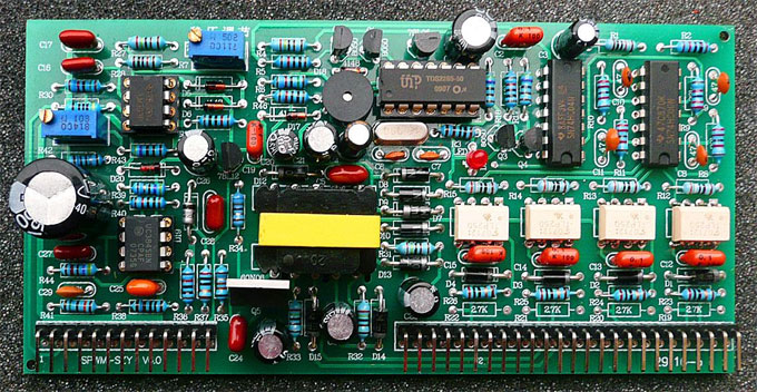
This power inverter is designed for 12v DC, but also can be connected to 24v DC, my goal is 800 watt, strive to 1000 watt pure sine wave output. The home inverter overall structure is, downside is a large cooling plate, upside is a power board with same size as the cooling plate, length 228mm, width 140mm. 4 power tubes of voltage boost portion, 4 power tubes of H-bridge and 4 TO220 packed fast diodes are screwed on the cooling plate directly; DC-DC voltage boost circuit driver board and SPWM driver board are plugged on the power motherboard.
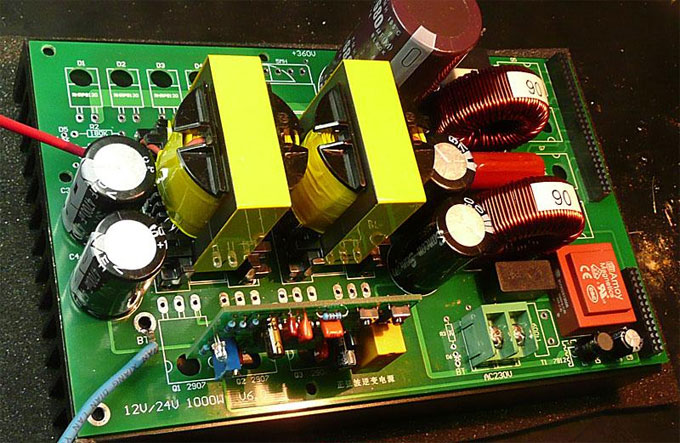
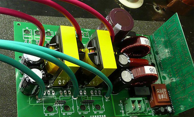
Due to the high current, soldered three pairs 6mm2 cords to the power panel of the home inverter.
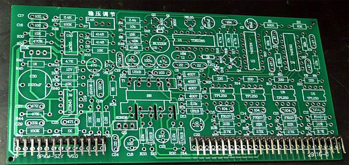
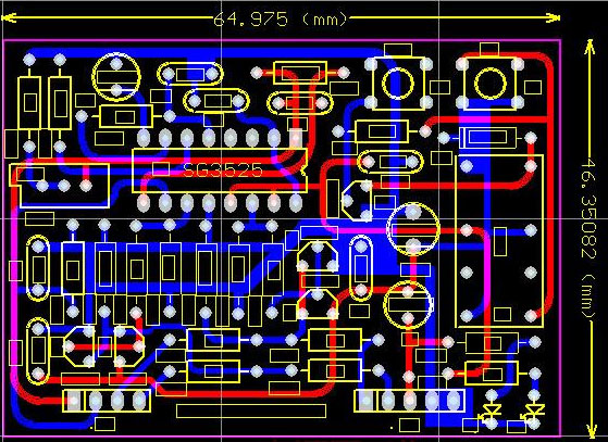
Learn a lesson from previous experiences: In previous designs, the inverter PCB design was not good enough before spending a lot of time and money to make samples. So, I fully take into account of the PCB board flexibility in drawings for this home power inverter, using one board for multi-purposes, and then the cost is lower.
Show as above picture: reserve a position for an inductor on the PCB board, in general, it's quasi open loop, do not install the inductor, direct connected, if you use a close loop voltage regulation, install an EC35 inductor on this position.
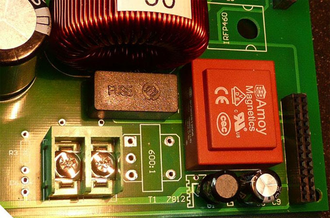
The red component on above picture is a 0.6 watt sampling transformer, if using differential sampling, this position can be installed two 200k dropping resistors. On the left side of the sampling transformer, there is a place like a small transformer is the reserved position for current transformer. There is no current feedback for this home power inverter, so it's not equipped the current transformer, it's connected under the PCB directly.
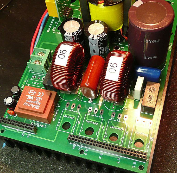
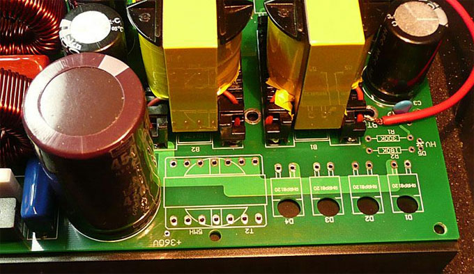
Above picture is the interface of the inverter SPWM driver board, four holes are used for installing 4 power tubes of the H-bridge. The white component is 0.1R current sampling resistor. Two 40 diameter filter inductors are winding with 1.18 wire for around 90 circles, inductance is about 1MH, initial magnetic permeability is 90.
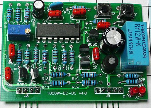
Above picture is the inverter DC-DC voltage boost driver circuit, using KA3525. There are two circuits installed for this power inverter, one is 27k frequency, for ordinary transformer drive, the other one is 16k, to try the effect of amorphous magnetic transformer.
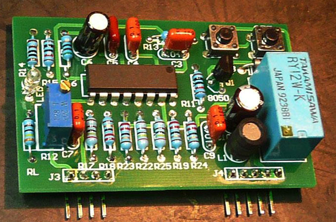
This is the inverter SPWM driver PCB board, the scheme is using microcontroller SPWM TDS2285 chip, the output is driven by 250 optical coupling, as it is more reliable. Also, the two tubes do not use bootstrap power supply, but with the three sets isolated power supply to the optical coupling. Due to the small transformer is delayed, so this board has not been installed. The SPWM driver in this scheme is flexible, either MCU, or use pure hardware, as long as the driver board interfaces are designed to be consistent, it can be plugged into a power board of this scheme, and even can be made into a square wave inverter.
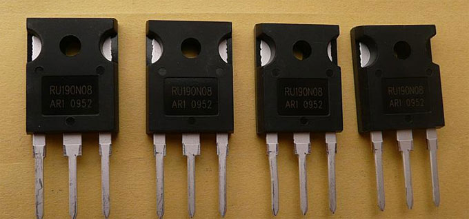
The big tubes of DC-DC power section are not 2907, but RU190N08, as this tube is slightly cheaper than 2907, so it worth to take a try.
There are two options for the high-power tube of H-bridge, one is commonly used IRFP460, the other one is IGBT 40N60, obviously they are not the same grade tubes, 40N60 is much more expensive, but indeed, I feel 40N60 is much more reliable.
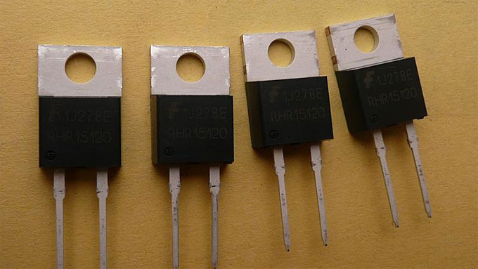
These are fast recovery packed diodes TO220, 15A 1200V, the price is affordable. I think the cooling effect is certainly stronger than ordinary plastic pipe diodes.
The transformer is winding with two EC49 cores, each power is 500 watt, the margin should be relative large, primary is parallel and secondary is series. The reasons of using two transformers: 1, benefits for the power output; 2, the ratio of transformation becomes smaller, and then the spike problems may have less headaches.
September 2, 2015
Today, I try to power on the former stage, but not succeed at the first time. No-load current is nearly 1A, troubleshooting reason is the transformer, then change the transformer core, and no-load decrease to 360MA (180MH of each transformer, which is accepted), obviously the importance of the transformer core, and it's difficult to buy a few pair good cores. Fortunately, D pole has good waveform, the transformer parameters are: Primary 3 + 3, with copper 0.2 * 29, secondary 44T, with 0.74 two lines. The next step is preparing loading for former stage, the former stage quality is the key factor for a home inverter to output prospective power. There is a little problem of the high-power switching power supply needs to be solved, so it may take few days for loading test.
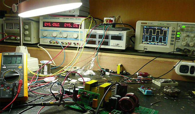
The current of the regulated power supply on the picture shows 450MA, because it's not completely no-load, I add a LED to it, with 150K2W resistance for voltage reduction, this indicator circuit consumes nearly 1 watt power, increases about 90MA current.
September 8, 2015
Today, add load to test the inverter former stage which is open-loop, and no inductor installed, there are two steps:
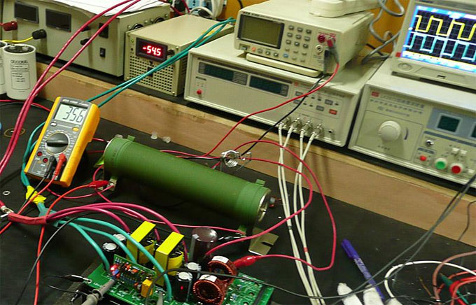
Step One: Loading about 630 watt, the load is a 200R, 1000 watt resistance, the operating current is 54.5A. Continuous work for one hour, the temperature of the cooling plate, 190N08 power tube and transformer only rise a little, D pole waveform is still good, spikes just expose, but not obvious, the bus voltage is 356V.
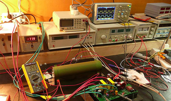
Step two: increasing the load with two 200 watt bulbs in series, then the operating current is about 77.9A, and the actual output power is 900 watt or more, the bus voltage drop to 347V, D pole waveform has spikes. Work for half an hour, the home inverter cooling plate temperature is 45℃, 4 unit 190N08 temperature: 3 units are 46℃, the rest one is 51℃, the transformer is also a bit of heating, but fast diode is not hot at all.
If the power inverter output 1000w, the former stage should be 1100 watt at least. From today's situation, the temperature seems to rise a bit faster, the temperature increase mainly in the high-power MOS tube and transformer. The heating of transformer, I still think the core quality is critical, the current of each transformer unilateral winding is less than 20A in 900 watt, I use 0.2x29mm copper, 5.8mm2, the current density has 3A only, the primary winding is not supposed to hot; The secondary has 0.74x2, the current is less than 3A in 900 watt, should not be hot too. It seems the transformer core is so important.
I will use a fan to cooling the plate initiative to load 1000 watt or more.
September 29, 2015
Today, continue to increase the loads by adding two 150 watt bulbs in series, the power supply voltage is increased 0.2V when considering the line voltage drops in large current, it is 12.4V, but the power line has 12.1V only (The power cord is using two 10mm2 paralleling). When turn on the power inverter, the current reaches 98.7A, the bus voltage is 345V, the bus current is 3.151A, the actual output power is 1087 watt. D pole spike waveform is somewhat heightened, reach 45Vpp. At this time, the power consumption reaches 1194 watt, the former stage actual efficiency is 91% only. The temperature of transformer is raised obviously, as I put a small fan under the cooling plate, so the temperature of the tube is below 40℃, I just let the home inverter work for about 20 minutes.
Summary: the former stage testing is not finished, I would like to do the testing with nanocrystalline magnet, but certainly there is no time in this month. The main bottlenecks to improve the power and efficiency at 12 volt is: 1. Transformer, include the core quality, winding technology etc.; 2. High-power MOS tube, the resistance must be low; 3. Wiring and structure, The large current path of the PCB opposite has 15-20mm wide copper foil, fill 2mm tin, and add a few 4mm2 copper wire, the structure is mainly the heat must be smooth, add a small fan is a good approach.
October 12, 2015
Today, just trying to make a comparison test between RU190N08 and 2907, testing the inverter efficiency of these two tubes under different output power, then, adjusting a variety of test instruments, testing the RU190N08 which was already installed on the board, the test results show as follow, the power inverter efficiency is in good condition.
The next step is spending more than one hour to change the tubes, equip with four new IRFP2907, turn on the power inverter excitedly, hope it has a good result, but ------ failed!
While loading two 150 watt bulbs in series, operating current is 41.5A, input power is 523.3 watt, output power is 283.4 watt, the home inverter efficiency is only: 54%. This is not the expected result, 2907 tubes heating quickly.
For this unexpected result, I check the D pole waveform, unexpectedly it appears long spikes:
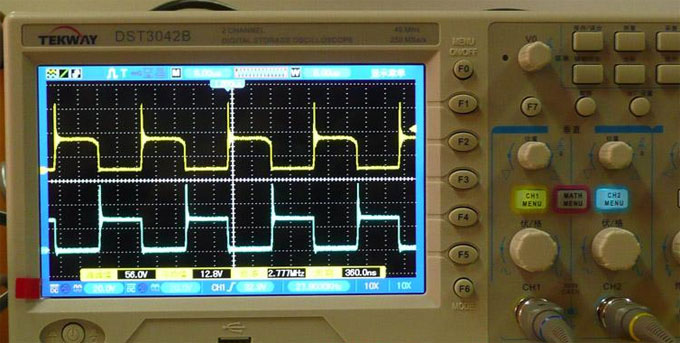
Generally, for such a waveform, it's certainly suspecting the transformer leakage inductance is too big, but the two transformers with RU190N08 were working well, there was no spike with the same loads.
Then, I measure the waveform of G pole, and find out the driven square wave all become trapezoidal wave, suddenly I realize it was the lack of drive power of 2907 tubes. It seems the junction capacitance of 2907 is much larger than RU190N08, it's difficult to drive four 2907 by 3525 directly. In order to confirm my thoughts, I replace the original grid resistor 20R to 10R, then power on the home inverter, in the same load condition, the current drops to 28.3A (with RU190N08 it's 21.9A only), of course it's under excitation because the driver board is not installed totem pole output, now we had to hold the testing until re-do the driver board.
(If the drive power is shortage, D pole will show up long spikes, this is the first encounter, good experience, ah!)

Above picture is the grid waveform, the resistor has been replaced to 10R, it will be worse if it's 20R.
The picture is the waveform measured on 11, 14 feet of 3525, it's a little deformed.
October 18, 2015
Today, spend a whole day to re-draw the DC-DC driver board with a totem pole output.
October 25, 2015
Today, the inverter DC-DC driver board PCB with totem pole output has finally completed, and equip with one for testing.
Because the addition of the totem pole output, the under-excitation of 2907 is greatly improved, but when the no-load current is higher than 190N08, never mind, continue to the testing.
The following table is the comparison of 2907 and 190N80
November 2, 2015
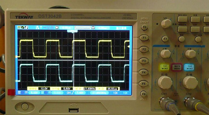
The picture is the new installed SPWM driven board, it works great after testing.
November 5, 2015
Today, equip with the SPWM driver board and turn on the power inverter, the protection circuit malfunction unexpectedly, the buzzer beeps, then troubleshooting for a while, change the values of several components, the problem is solved.
Starting up is successful, the sine wave form is good, the loads are two 200 watt bulbs and one 150 watt bulb, the electrical parameter analyzer displays the output power is 617 watt, the efficiency at this time is around 91.5-92 % (Unfortunately, the no-load current is slightly higher, make a bit affection on the efficiency).
I was planning to increase the load to about 1000 watt tomorrow, but found out a problem, the voltage regulated part does not work, adjust the potentiometer but no action, then troubleshooting and find that the beautiful sampling transformer has no output, it's dispirited.
November 14, 2015
Today, this 1000w home inverter finally enters into the end stage. It takes nearly two hours to check the voltage unregulated reason, and finally find the clue of the problem, it is a flash of the PCB to make the sampling transformer secondary grounded, maybe the impedance of 0.6 watt transformer is too high, it's not burn out. After repairing the PCB, the voltage regulate function is working, adjust the output in no-load to about 230V, everything is OK!
Then buy a few bulbs in afternoon, increase the load slowly till 1000 watt, continuously work 30 minutes, except the temperature of the high-frequency transformer increase a bit, all the rest parts are normal (Put a small fan under the inverter cooling plate).
In 1039 watt output, the efficiency is about 90% - 90.5%, from the view of transformer heating situation, the efficiency bottleneck of this home power inverter is the transformer or transformer core, if there is a good quality transformer, the efficiency should be improved.
Electrical parameter analyzer displays 1035 watt, bouncing between 1035 and 1039.
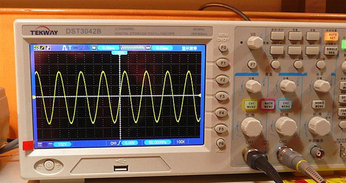
This is the waveform of 1000w load output, still very beautiful!
November 16, 2015
Today, do two jobs:
1. Adjust the former stage of the inverter DC-DC voltage boost part, adjust R12 to make the HV maximum voltage limit at 370v, then, the no-load current down from nearly 1A to 160mA, plus the 140mA of SPWM driver board, total is 300mA.
2. Try it with inductive load, connect a 600 watt angle grinder to the power inverter, the waveform is same as bulbs, no distortion.
Now I'm thinking: whether it can drive around 100 liters refrigerator.
Here are the circuit schemes of this 1000 watt home inverter, maybe not mature, just for reference:
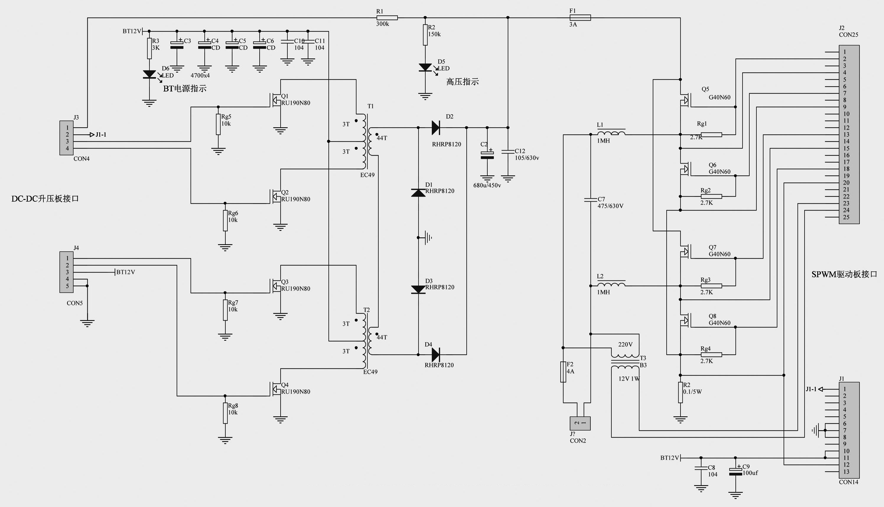
DC-DC voltage boost section circuit diagram, using RU190N08
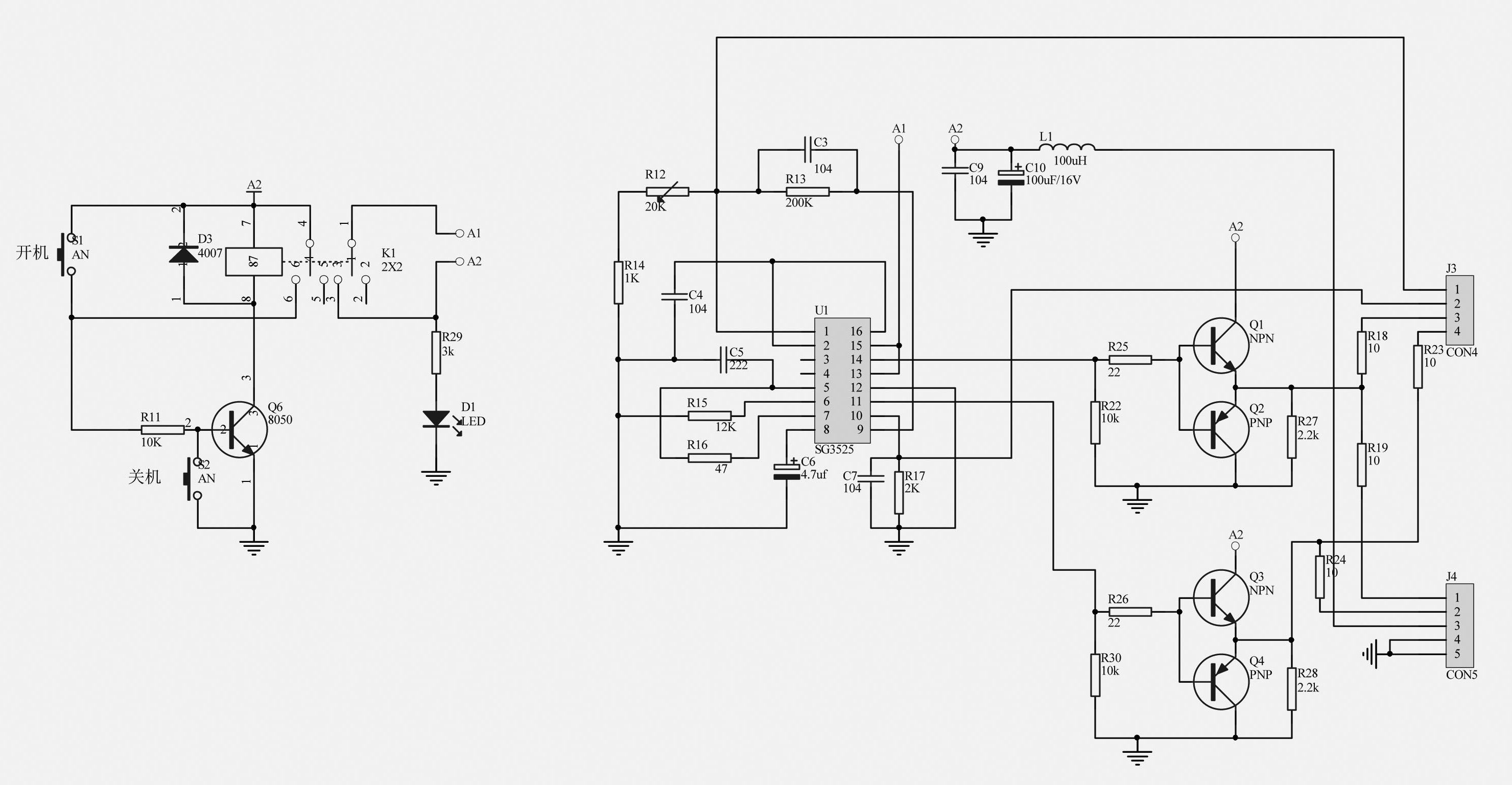
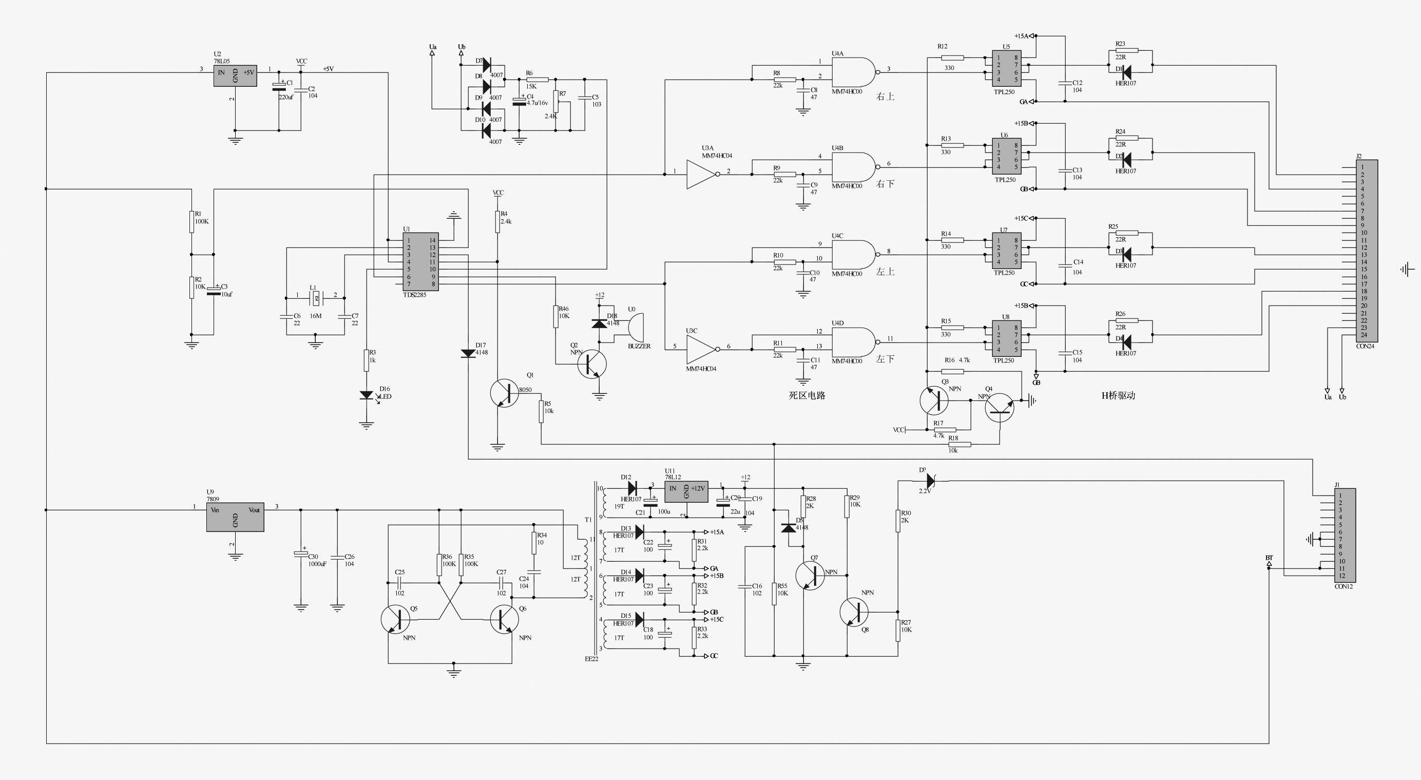
Master board circuit diagram
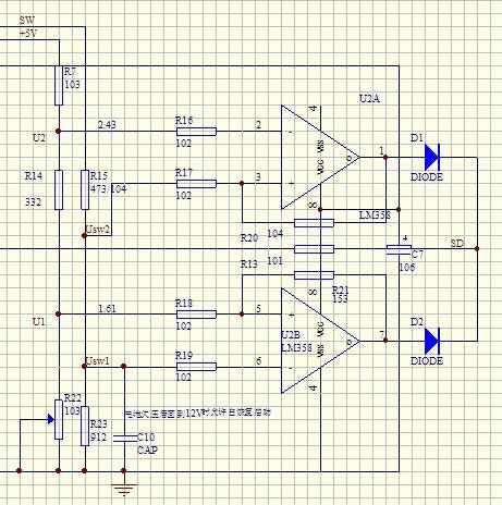
SPWM driven circuit diagram
Paper original source: http://www.gohz.com/12v-1000w-inverter-design-process
Due to the high current, soldered three pairs 6mm2 cords to the power panel of the home inverter.
Learn a lesson from previous experiences: In previous designs, the inverter PCB design was not good enough before spending a lot of time and money to make samples. So, I fully take into account of the PCB board flexibility in drawings for this home power inverter, using one board for multi-purposes, and then the cost is lower.
Show as above picture: reserve a position for an inductor on the PCB board, in general, it's quasi open loop, do not install the inductor, direct connected, if you use a close loop voltage regulation, install an EC35 inductor on this position.
The red component on above picture is a 0.6 watt sampling transformer, if using differential sampling, this position can be installed two 200k dropping resistors. On the left side of the sampling transformer, there is a place like a small transformer is the reserved position for current transformer. There is no current feedback for this home power inverter, so it's not equipped the current transformer, it's connected under the PCB directly.
Above picture is the interface of the inverter SPWM driver board, four holes are used for installing 4 power tubes of the H-bridge. The white component is 0.1R current sampling resistor. Two 40 diameter filter inductors are winding with 1.18 wire for around 90 circles, inductance is about 1MH, initial magnetic permeability is 90.
Above picture is the inverter DC-DC voltage boost driver circuit, using KA3525. There are two circuits installed for this power inverter, one is 27k frequency, for ordinary transformer drive, the other one is 16k, to try the effect of amorphous magnetic transformer.
This is the inverter SPWM driver PCB board, the scheme is using microcontroller SPWM TDS2285 chip, the output is driven by 250 optical coupling, as it is more reliable. Also, the two tubes do not use bootstrap power supply, but with the three sets isolated power supply to the optical coupling. Due to the small transformer is delayed, so this board has not been installed. The SPWM driver in this scheme is flexible, either MCU, or use pure hardware, as long as the driver board interfaces are designed to be consistent, it can be plugged into a power board of this scheme, and even can be made into a square wave inverter.
The big tubes of DC-DC power section are not 2907, but RU190N08, as this tube is slightly cheaper than 2907, so it worth to take a try.
There are two options for the high-power tube of H-bridge, one is commonly used IRFP460, the other one is IGBT 40N60, obviously they are not the same grade tubes, 40N60 is much more expensive, but indeed, I feel 40N60 is much more reliable.
These are fast recovery packed diodes TO220, 15A 1200V, the price is affordable. I think the cooling effect is certainly stronger than ordinary plastic pipe diodes.
The transformer is winding with two EC49 cores, each power is 500 watt, the margin should be relative large, primary is parallel and secondary is series. The reasons of using two transformers: 1, benefits for the power output; 2, the ratio of transformation becomes smaller, and then the spike problems may have less headaches.
September 2, 2015
Today, I try to power on the former stage, but not succeed at the first time. No-load current is nearly 1A, troubleshooting reason is the transformer, then change the transformer core, and no-load decrease to 360MA (180MH of each transformer, which is accepted), obviously the importance of the transformer core, and it's difficult to buy a few pair good cores. Fortunately, D pole has good waveform, the transformer parameters are: Primary 3 + 3, with copper 0.2 * 29, secondary 44T, with 0.74 two lines. The next step is preparing loading for former stage, the former stage quality is the key factor for a home inverter to output prospective power. There is a little problem of the high-power switching power supply needs to be solved, so it may take few days for loading test.
The current of the regulated power supply on the picture shows 450MA, because it's not completely no-load, I add a LED to it, with 150K2W resistance for voltage reduction, this indicator circuit consumes nearly 1 watt power, increases about 90MA current.
September 8, 2015
Today, add load to test the inverter former stage which is open-loop, and no inductor installed, there are two steps:
Step One: Loading about 630 watt, the load is a 200R, 1000 watt resistance, the operating current is 54.5A. Continuous work for one hour, the temperature of the cooling plate, 190N08 power tube and transformer only rise a little, D pole waveform is still good, spikes just expose, but not obvious, the bus voltage is 356V.
Step two: increasing the load with two 200 watt bulbs in series, then the operating current is about 77.9A, and the actual output power is 900 watt or more, the bus voltage drop to 347V, D pole waveform has spikes. Work for half an hour, the home inverter cooling plate temperature is 45℃, 4 unit 190N08 temperature: 3 units are 46℃, the rest one is 51℃, the transformer is also a bit of heating, but fast diode is not hot at all.
If the power inverter output 1000w, the former stage should be 1100 watt at least. From today's situation, the temperature seems to rise a bit faster, the temperature increase mainly in the high-power MOS tube and transformer. The heating of transformer, I still think the core quality is critical, the current of each transformer unilateral winding is less than 20A in 900 watt, I use 0.2x29mm copper, 5.8mm2, the current density has 3A only, the primary winding is not supposed to hot; The secondary has 0.74x2, the current is less than 3A in 900 watt, should not be hot too. It seems the transformer core is so important.
I will use a fan to cooling the plate initiative to load 1000 watt or more.
September 29, 2015
Today, continue to increase the loads by adding two 150 watt bulbs in series, the power supply voltage is increased 0.2V when considering the line voltage drops in large current, it is 12.4V, but the power line has 12.1V only (The power cord is using two 10mm2 paralleling). When turn on the power inverter, the current reaches 98.7A, the bus voltage is 345V, the bus current is 3.151A, the actual output power is 1087 watt. D pole spike waveform is somewhat heightened, reach 45Vpp. At this time, the power consumption reaches 1194 watt, the former stage actual efficiency is 91% only. The temperature of transformer is raised obviously, as I put a small fan under the cooling plate, so the temperature of the tube is below 40℃, I just let the home inverter work for about 20 minutes.
Summary: the former stage testing is not finished, I would like to do the testing with nanocrystalline magnet, but certainly there is no time in this month. The main bottlenecks to improve the power and efficiency at 12 volt is: 1. Transformer, include the core quality, winding technology etc.; 2. High-power MOS tube, the resistance must be low; 3. Wiring and structure, The large current path of the PCB opposite has 15-20mm wide copper foil, fill 2mm tin, and add a few 4mm2 copper wire, the structure is mainly the heat must be smooth, add a small fan is a good approach.
October 12, 2015
Today, just trying to make a comparison test between RU190N08 and 2907, testing the inverter efficiency of these two tubes under different output power, then, adjusting a variety of test instruments, testing the RU190N08 which was already installed on the board, the test results show as follow, the power inverter efficiency is in good condition.
| Item | Loads | RU190N08 | ||||||
| Input Voltage (V) | Input Current (A) | Input Power (W) | Bus Voltage (V) | Bus Current (A) | Output Power (W) | Efficiency (%) | ||
| 1 | Two 150 watt bulbs in series | 12.59 | 21.9 | 275.7 | 374 | 0.71 | 265.5 | 96.3 |
| 2 | Two 200 watt bulbs in series | 12.58 | 25.6 | 322 | 373 | 0.835 | 311.5 | 96.7 |
| 3 | 200R high-power resistor | 12.49 | 53 | 662 | 361 | 1.742 | 628.9 | 95 |
| 4 | 200R resistor + 2x200w bulbs | 12.44 | 72.7 | 904.1 | 353 | 2.392 | 844.4 | 93.4 |
| 5 | 200R resistor + 2x200w bulbs + 2x150w bulbs | 12.37 | 95.1 | 1176.4 | 343 | 3.136 | 1075.6 | 91.4 |
The next step is spending more than one hour to change the tubes, equip with four new IRFP2907, turn on the power inverter excitedly, hope it has a good result, but ------ failed!
While loading two 150 watt bulbs in series, operating current is 41.5A, input power is 523.3 watt, output power is 283.4 watt, the home inverter efficiency is only: 54%. This is not the expected result, 2907 tubes heating quickly.
For this unexpected result, I check the D pole waveform, unexpectedly it appears long spikes:
Generally, for such a waveform, it's certainly suspecting the transformer leakage inductance is too big, but the two transformers with RU190N08 were working well, there was no spike with the same loads.
Then, I measure the waveform of G pole, and find out the driven square wave all become trapezoidal wave, suddenly I realize it was the lack of drive power of 2907 tubes. It seems the junction capacitance of 2907 is much larger than RU190N08, it's difficult to drive four 2907 by 3525 directly. In order to confirm my thoughts, I replace the original grid resistor 20R to 10R, then power on the home inverter, in the same load condition, the current drops to 28.3A (with RU190N08 it's 21.9A only), of course it's under excitation because the driver board is not installed totem pole output, now we had to hold the testing until re-do the driver board.
(If the drive power is shortage, D pole will show up long spikes, this is the first encounter, good experience, ah!)
Above picture is the grid waveform, the resistor has been replaced to 10R, it will be worse if it's 20R.
The picture is the waveform measured on 11, 14 feet of 3525, it's a little deformed.
October 18, 2015
Today, spend a whole day to re-draw the DC-DC driver board with a totem pole output.
October 25, 2015
Today, the inverter DC-DC driver board PCB with totem pole output has finally completed, and equip with one for testing.
Because the addition of the totem pole output, the under-excitation of 2907 is greatly improved, but when the no-load current is higher than 190N08, never mind, continue to the testing.
The following table is the comparison of 2907 and 190N80
| Item | Loads | IRFP2907 | RU190N08 | ||||||||||||
| Input Voltage (V) | Input Current (A) | Input Power (W) | Bus Voltage (V) | Bus Current (A) | Output Power (W) | Efficiency (%) | Input Voltage (V) | Input Current (A) | Input Power (W) | Bus Voltage (V) | Bus Current (A) | Output Power (W) | Efficiency (%) | ||
| 1 | Two 150 watt bulbs in series | 12.58 | 22.6 | 284.3 | 376 | 0.712 | 267.7 | 94.2 | 12.59 | 21.9 | 275.7 | 374 | 0.71 | 265.5 | 96.3 |
| 2 | Two 200 watt bulbs in series | 12.57 | 26.1 | 328.1 | 374 | 0.829 | 310 | 94.5 | 12.58 | 25.6 | 322 | 373 | 0.835 | 311.5 | 96.7 |
| 3 | 200R high-power resistor | 12.48 | 54.2 | 676.4 | 364 | 1.757 | 639.5 | 94.6 | 12.49 | 53 | 662 | 361 | 1.742 | 628.9 | 95 |
| 4 | 200R resistor + 2x200w bulbs | 12.42 | 77.7 | 965 | 356 | 2.528 | 900 | 93.2 | 12.44 | 72.7 | 904.1 | 353 | 2.392 | 844.4 | 93.4 |
| 5 | 200R resistor + 2x200w bulbs + 2x150w bulbs | 12.36 | 97.3 | 1202.6 | 349 | 3.175 | 1108 | 92.1 | 12.37 | 95.1 | 1176.4 | 343 | 3.136 | 1075.6 | 91.4 |
November 2, 2015
The picture is the new installed SPWM driven board, it works great after testing.
November 5, 2015
Today, equip with the SPWM driver board and turn on the power inverter, the protection circuit malfunction unexpectedly, the buzzer beeps, then troubleshooting for a while, change the values of several components, the problem is solved.
Starting up is successful, the sine wave form is good, the loads are two 200 watt bulbs and one 150 watt bulb, the electrical parameter analyzer displays the output power is 617 watt, the efficiency at this time is around 91.5-92 % (Unfortunately, the no-load current is slightly higher, make a bit affection on the efficiency).
I was planning to increase the load to about 1000 watt tomorrow, but found out a problem, the voltage regulated part does not work, adjust the potentiometer but no action, then troubleshooting and find that the beautiful sampling transformer has no output, it's dispirited.
November 14, 2015
Today, this 1000w home inverter finally enters into the end stage. It takes nearly two hours to check the voltage unregulated reason, and finally find the clue of the problem, it is a flash of the PCB to make the sampling transformer secondary grounded, maybe the impedance of 0.6 watt transformer is too high, it's not burn out. After repairing the PCB, the voltage regulate function is working, adjust the output in no-load to about 230V, everything is OK!
Then buy a few bulbs in afternoon, increase the load slowly till 1000 watt, continuously work 30 minutes, except the temperature of the high-frequency transformer increase a bit, all the rest parts are normal (Put a small fan under the inverter cooling plate).
In 1039 watt output, the efficiency is about 90% - 90.5%, from the view of transformer heating situation, the efficiency bottleneck of this home power inverter is the transformer or transformer core, if there is a good quality transformer, the efficiency should be improved.
Electrical parameter analyzer displays 1035 watt, bouncing between 1035 and 1039.
This is the waveform of 1000w load output, still very beautiful!
November 16, 2015
Today, do two jobs:
1. Adjust the former stage of the inverter DC-DC voltage boost part, adjust R12 to make the HV maximum voltage limit at 370v, then, the no-load current down from nearly 1A to 160mA, plus the 140mA of SPWM driver board, total is 300mA.
2. Try it with inductive load, connect a 600 watt angle grinder to the power inverter, the waveform is same as bulbs, no distortion.
Now I'm thinking: whether it can drive around 100 liters refrigerator.
Here are the circuit schemes of this 1000 watt home inverter, maybe not mature, just for reference:
DC-DC voltage boost section circuit diagram, using RU190N08
Master board circuit diagram
SPWM driven circuit diagram
Paper original source: http://www.gohz.com/12v-1000w-inverter-design-process
I have an energy cell thats output is tunable to the output EMF as needed, since its natural output is DC then an inverter is required for AC availability.
My energy cell outputs DC only so for AC an inverter is required.
Hello sir please I'm enjoying your inverter please can please send me the pcb of the spwm stage thank you
Please provide the list of components
i want a inverter circuit board for home purpose
Post a Comment:
You may also like:

Power Inverter Source
Featured Articles
How to Choose a Suitable Power ...
 How to select the inverter for an air conditioner, television, computer or the motor? How to match the battery? How long is the ...
How to select the inverter for an air conditioner, television, computer or the motor? How to match the battery? How long is the ...12V 300W Uni-polar Isolation Pure Sine ...
 12v 300w uni-polar isolation of pure sine wave inverter Basic parameters Nominal power: 300W; continuous power: 250W; Peak power: ...
12v 300w uni-polar isolation of pure sine wave inverter Basic parameters Nominal power: 300W; continuous power: 250W; Peak power: ...600w Pure Sine Wave Power Inverter ...
 I spent nearly a month design a 600w pure sine wave power inverter. The machine has the following characteristics: 1. SPWM drive ...
I spent nearly a month design a 600w pure sine wave power inverter. The machine has the following characteristics: 1. SPWM drive ...1000w 12V DC Home Power Inverter ...
This power inverter is designed for 12v DC, but also can be connected to 24v DC, my goal is 800 watt, strive to 1000 watt pure ...
This power inverter is designed for 12v DC, but also can be connected to 24v DC, my goal is 800 watt, strive to 1000 watt pure ...