High Voltage Inverter Design
Along with the wider application of PWM technology used in inverting and the inverse frequency fields, as well as the rapid development of IGBT, MOSFET and other power switching device of such PWM control of high-voltage power supply toward miniaturization, high frequency, intelligent, high efficiency direction.
For this power inverter, a voltage pulse mode PWM controller IC SG3525A, high pressure suspension and drive IR2110, high frequency inverter with power switching device IGBT module program. In addition, the MCU control technology to control this power, so that the whole system is simple, and the realization of the digital intelligent systems.
SG3525A performance and structure
SG3525A is a voltage type PWM integrated controller. It has advantages of less external components, good performance, including all required switching regulator control circuit. Key features include: external synchronization, soft start function, dead zone adjustment, under-voltage lockout, and the closure of the error amplifier output drive signal and other functions; push-pull output stage circuit structure, off speed, output current of ±400mA; It provides precision of 5V±1% reference voltage; Switching frequency range of 100Hz~400kHz.
Its internal structure includes a reference voltage source, under-voltage lockout circuit, saw-tooth oscillator, error amplifier, as shown in figure 1.

Figure 1/SG3525A internal block diagram and pin functions
IR2110 performance and structure
IR2110 is using HVIC and latch immunity manufacturing process, moreover, integrating DIP, SOIC package. Key features include: suspension channel supply bootstrap circuit voltage up to 500V; power device gate drive voltage range of 10V~20V; peak output current of 2A; logic supply range 5V~20V, and logic ground and power supply allow between the 5V offset; COMS Schmitt inputs with pull-down resistor, you can easily and LSTTL and CMOS level matching; separate low and high input channels with voltage and lock the two channels function; matching two-channel delay of 10ns; switch-off delay is small, were 120ns and 90ns; operating frequency of 500kHz.
Its internal structure includes input logic level conversion and output protection, as shown in figure 2.

Figure 2/IR2110 internal block diagram and pin functions
Design Principles
Suspended high side driver bootstrap principle
IR2110 half-bridge driving circuit is shown in figure 3. In the figure, C1, VD1 were bootstrap capacitor and diode, C2 to VCC filter capacitor. During the shutdown assumed S1, C1 has been charged to a sufficient voltage VC1≈VCC. When HIN is high, VM1 opening, VM2 off, VC1 applied to S1 between the gate and emitter, C1 through VM1, Rg1 and S1 gate capacitance Cgc1 discharge, Cgc1 is charged. At this point VC1 is equivalent to a voltage source. When HIN is low, VM2 opened, VM1 off, S1 gate charge by Rg1, VM2 quick release, S1 is turned off. After a short dead time (td) by, LIN is high, S2 opened, VCC through VD1, S2 to charge C1 to C1 quickly replenish energy. So the cycle repeated.

Figure 3/Half-bridge driver bootstrap circuit
Bootstrap component design
Bootstrap diode (VD1) and a capacitor (C1) is a rigorous selection and design needs IR2110 in PWM application components should be adjusted so that the circuit according to certain rules in the best condition.
At the same time, the choice of the bootstrap capacitor size should be considered suspended driver widest on-time ton (max) and the narrowest on-time ton (min). Conduction time should neither be too high to effect driving performance narrower pulse width, and cannot be too low to affect the pulse drive requirements. According to the operating frequency of power devices, switching speed, characteristic of the gate turn-on time is selected, it estimates given by debugging.
VD1 mainly used for blocking HVDC trunk, which is to withstand the current gate charge and switching frequency of the product. To reduce the charge loss, should choose the reverse leakage current of the diode.
SG3525A main circuit using high-frequency inverter and constituted IR2110
High frequency inverter main circuit is shown in figure 4. The inverter high-voltage full bridge drives routing components. Power switch Q1~Q4 IGBT power modules. Inverter main circuit DC voltage V1 is converted to a high frequency square wave AC voltage is supplied to 20kHz frequency high-voltage transformer T1, after the boost rectifier to provide power to the load. By controlling circuit PWM1 and PWM2 duty cycle, pulse width adjustable to obtain a rectangular wave AC voltage. VF high-voltage sense input voltage is fed back to the control system.

Figure 4/High voltage inverter main circuit
SCM control system
Figure 5 shows the complete block diagram of the high voltage inverter power system, which includes two parts, the main circuit and control circuit. The main circuit includes an inverter DC power supply, IGBT bridge inverter, protection circuits, high frequency high voltage transformers, high frequency high voltage silicon stack (Rectifier) and the like. The control circuit includes a current, voltage sampling and processing unit, PWM signal generation and a driver circuit, micro-controller, keyboard and LCD parameter input, part of the communications interface. In order to better solve the interference system, isolation, electromagnetic compatibility and other issues, in the control section and the main circuit is completely isolated optocoupler.
This hardware system coupled software and make the whole system has a complete user interface and intelligent features such as self-diagnosis.

Figure 5/SCM inverter control system
Epilogue
By the PWM control chip and high voltage driver IR2110 SG3525A consisting frequency inverter, small size, easy to control, energy utilization efficiency. This system has now been used in high-frequency power supply medical equipment.
For this power inverter, a voltage pulse mode PWM controller IC SG3525A, high pressure suspension and drive IR2110, high frequency inverter with power switching device IGBT module program. In addition, the MCU control technology to control this power, so that the whole system is simple, and the realization of the digital intelligent systems.
SG3525A performance and structure
SG3525A is a voltage type PWM integrated controller. It has advantages of less external components, good performance, including all required switching regulator control circuit. Key features include: external synchronization, soft start function, dead zone adjustment, under-voltage lockout, and the closure of the error amplifier output drive signal and other functions; push-pull output stage circuit structure, off speed, output current of ±400mA; It provides precision of 5V±1% reference voltage; Switching frequency range of 100Hz~400kHz.
Its internal structure includes a reference voltage source, under-voltage lockout circuit, saw-tooth oscillator, error amplifier, as shown in figure 1.
Figure 1/SG3525A internal block diagram and pin functions
IR2110 performance and structure
IR2110 is using HVIC and latch immunity manufacturing process, moreover, integrating DIP, SOIC package. Key features include: suspension channel supply bootstrap circuit voltage up to 500V; power device gate drive voltage range of 10V~20V; peak output current of 2A; logic supply range 5V~20V, and logic ground and power supply allow between the 5V offset; COMS Schmitt inputs with pull-down resistor, you can easily and LSTTL and CMOS level matching; separate low and high input channels with voltage and lock the two channels function; matching two-channel delay of 10ns; switch-off delay is small, were 120ns and 90ns; operating frequency of 500kHz.
Its internal structure includes input logic level conversion and output protection, as shown in figure 2.
Figure 2/IR2110 internal block diagram and pin functions
Design Principles
Suspended high side driver bootstrap principle
IR2110 half-bridge driving circuit is shown in figure 3. In the figure, C1, VD1 were bootstrap capacitor and diode, C2 to VCC filter capacitor. During the shutdown assumed S1, C1 has been charged to a sufficient voltage VC1≈VCC. When HIN is high, VM1 opening, VM2 off, VC1 applied to S1 between the gate and emitter, C1 through VM1, Rg1 and S1 gate capacitance Cgc1 discharge, Cgc1 is charged. At this point VC1 is equivalent to a voltage source. When HIN is low, VM2 opened, VM1 off, S1 gate charge by Rg1, VM2 quick release, S1 is turned off. After a short dead time (td) by, LIN is high, S2 opened, VCC through VD1, S2 to charge C1 to C1 quickly replenish energy. So the cycle repeated.
Figure 3/Half-bridge driver bootstrap circuit
Bootstrap component design
Bootstrap diode (VD1) and a capacitor (C1) is a rigorous selection and design needs IR2110 in PWM application components should be adjusted so that the circuit according to certain rules in the best condition.
At the same time, the choice of the bootstrap capacitor size should be considered suspended driver widest on-time ton (max) and the narrowest on-time ton (min). Conduction time should neither be too high to effect driving performance narrower pulse width, and cannot be too low to affect the pulse drive requirements. According to the operating frequency of power devices, switching speed, characteristic of the gate turn-on time is selected, it estimates given by debugging.
VD1 mainly used for blocking HVDC trunk, which is to withstand the current gate charge and switching frequency of the product. To reduce the charge loss, should choose the reverse leakage current of the diode.
SG3525A main circuit using high-frequency inverter and constituted IR2110
High frequency inverter main circuit is shown in figure 4. The inverter high-voltage full bridge drives routing components. Power switch Q1~Q4 IGBT power modules. Inverter main circuit DC voltage V1 is converted to a high frequency square wave AC voltage is supplied to 20kHz frequency high-voltage transformer T1, after the boost rectifier to provide power to the load. By controlling circuit PWM1 and PWM2 duty cycle, pulse width adjustable to obtain a rectangular wave AC voltage. VF high-voltage sense input voltage is fed back to the control system.
Figure 4/High voltage inverter main circuit
SCM control system
Figure 5 shows the complete block diagram of the high voltage inverter power system, which includes two parts, the main circuit and control circuit. The main circuit includes an inverter DC power supply, IGBT bridge inverter, protection circuits, high frequency high voltage transformers, high frequency high voltage silicon stack (Rectifier) and the like. The control circuit includes a current, voltage sampling and processing unit, PWM signal generation and a driver circuit, micro-controller, keyboard and LCD parameter input, part of the communications interface. In order to better solve the interference system, isolation, electromagnetic compatibility and other issues, in the control section and the main circuit is completely isolated optocoupler.
This hardware system coupled software and make the whole system has a complete user interface and intelligent features such as self-diagnosis.
Figure 5/SCM inverter control system
Epilogue
By the PWM control chip and high voltage driver IR2110 SG3525A consisting frequency inverter, small size, easy to control, energy utilization efficiency. This system has now been used in high-frequency power supply medical equipment.
Post a Comment:
You may also like:

Power Inverter Source
Featured Articles
How to Choose a Suitable Power ...
 How to select the inverter for an air conditioner, television, computer or the motor? How to match the battery? How long is the ...
How to select the inverter for an air conditioner, television, computer or the motor? How to match the battery? How long is the ...12V 300W Uni-polar Isolation Pure Sine ...
 12v 300w uni-polar isolation of pure sine wave inverter Basic parameters Nominal power: 300W; continuous power: 250W; Peak power: ...
12v 300w uni-polar isolation of pure sine wave inverter Basic parameters Nominal power: 300W; continuous power: 250W; Peak power: ...600w Pure Sine Wave Power Inverter ...
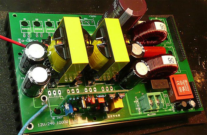
 I spent nearly a month design a 600w pure sine wave power inverter. The machine has the following characteristics: 1. SPWM drive ...
I spent nearly a month design a 600w pure sine wave power inverter. The machine has the following characteristics: 1. SPWM drive ...1000w 12V DC Home Power Inverter ...
 This power inverter is designed for 12v DC, but also can be connected to 24v DC, my goal is 800 watt, strive to 1000 watt pure ...
This power inverter is designed for 12v DC, but also can be connected to 24v DC, my goal is 800 watt, strive to 1000 watt pure ...