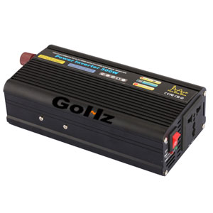
600w Pure Sine Wave Power Inverter Design
I spent nearly a month design a 600w pure sine wave power inverter. The machine has the following characteristics:


I. 600w pure sine wave power inverter Circuit principle:
The inverter is divided into four parts, each part make a PCB board. They are "power board", "SPWM driver board", "DC-DC driver board" and "protection board".
1. Power Board
Power board includes DC-DC push-pull booster and H-bridge inverter.
BT voltage of this power inverter is 12V, at full power, pre-operating current up to 55A above. DC-DC boost section with a pair of 190N08, this cow tube 247 package, as long as well cooling, a pair can output 600W, can also be used IRFP2907Z, output capacity is almost, the price is about the same. With the main transformer EE55 core, in fact, the 600W is concerned, with the EE42 is enough. To make convenience and the existing EE55 is there, on the use of EE55. On the main transformer winding, described in detail below. The power of supply Pre-Amp push-pull part adopts the symmetrical balance method, does this has two advantages. First, to ensure the symmetry of two large power tube current work status, and ensure that no unilateral fever phenomenon; the second is to reduce the current density PCB opposite stack tin layer. Of course, the interference can be greatly reduced because the current unbalance. High frequency high voltage rectifier diode using a TO220 package RHRP8120, these tubes is good reliability. High voltage filter capacitor is 470uf/450V, in possible, as far as possible with some of the large capacity, to improve the load characteristics of the high-pressure part and reduce interference as a whole.
H-bridge section using four IRFP460 withstand voltage 500v, maximum current 20A. Similar properties tubes can also be used instead, tubes with a small internal resistance can improve the overall efficiency of the inverter. Part of the H bridge circuit uses a conventional circuit.
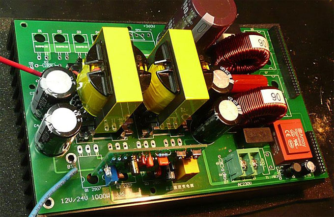
Here are 600 watt power inverter PCB shots of the power board, length and width is 200X150mm. Because this part of the circuit is relatively simple, so I did not draw schematics, PCB diagram is drawn directly.

2. 600w pure sine wave power inverter SPWM driver board
It is the same as my 1KW machine, the core part of the SPWM using the TDS2285 single chip. U3, U4 compose timing and dead circuit, the last stage output with four 250 optical coupling, two H-bridge works on the bootstrap supply. The aim is to simplify the circuit. You cannot isolate the power supply.
Because BT voltage will change between 10-15V, in order to reliably drive H-bridge, output stage voltage optical coupler 250 must be between 12-15V (no less than 12V), otherwise H bridge power tube trigger failure may occur. Here with a MC34063 (U9), the BT voltage to 15V. Experimental results show that this approach is very effective.
Entire SPWM driver board through J1, J2 socket turn on with the power board and pin as follows:
J2:
2P-4P; 7P-9P; 13P-15P; 18P-20P is respective drive pin H-bridge 4 power tube.
23P-24P is an input of AC power sampling voltage.
J1:
1P is 2285 output to pre-amp 3525 protection signal connection terminal of 10P. Once the protection circuit is activated, 12P output high of 2285, through the interface pin 10P to Pre-Amp 3525, close pre-amp output.
6P-7P-8P is GND.
9P connected to the output protection circuit for closing stage SPWM output.
10P-11P connected to BT power.
Here is 600 watt inverter PWM driver board electrical schematics and PCB screenshot:

3. 600w pure sine wave power inverter DC-DC driver board
600w pure sine wave power inverter DC-DC boost driver board, using a common line, with a SG3525 PWM realizes output, Poweramp output with two groups of totem. Experiment, if a pair of 190N08, totem part can be omitted, directly 3525 driven enough. This is because the DC-DC driver board and interface of my 1000W machine is versatile. So there are dual outputs, the machine is only a group. The board has two small buttons switch S1 and S2. S1 is for switching on, S2 is off, and they can control the start and stop of the inverter.
This driver board with J3, J4 interface connected to the power board, is the first 1P J3 limit voltage feedback input end.
The following is a DC-DC step-up driver circuit diagrams and PCB Screenshot:

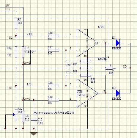
4. 600w pure sine wave power inverter Protection Board
I did not make protection board is the following reasons: First, there is no protection board the machine also can work; second is: The power board of publication was the revised afterwards, protection board interface also made changes. But I use the prototype is not corrected PCB board, even made a protection board, and could not get up. Here is a circuit diagram of part of the protection.
II. Main components making and purchasing
1. SPWM main chip

2. Main Transformer
Main transformer is the key to the success of the production of inverter, the machine main transformer with the core EE55, material PC40. Winding data: primary 2T plus 2T, with 10 lines 0.93. The total area of the primary wire 6.8 mm2, secondary is a 0.93 line, about 60T.


Power inverter winding preparation:
First, prepare the skeleton, cut off 4 pins, the red circle shows the cut pin. The two independent pins above are for high voltage winding. Away from beneath the pin conducive insulation, middle and bottom pins are used for low-voltage winding. Winding two laps left, 2 laps right.

Power inverter winding steps:
A) Wind a half the high voltage winding (secondary). On the first frame, stick a layer with high-temperature adhesive tape, which is to prevent wire slippage, wind a layer with a 0.93 for about 30 laps (thread to do the high voltage winding insulation), and then tape the thread, do not let it comes out. Out of the high voltage winding, pick three layer with heat tape.
B) Wind the low voltage winding (primary). Wind the low voltage winding separated into two layers. That is, each layer is 2 plus 2, 5-line winding. I drew a diagram (Figure below), I do not know if everyone can understand the structure.

First wind 2 laps with five 0.93 (Figure II red line), leaving gap in the middle, and then wind 2 laps in the gap with another five (Figure II blue line), each line is about 37CM. The same way to wind the two-story, inter-layer sticks two-story tape. This is equivalent to using a 10-line wind. After winding the low voltage, high-temperature tape sticks three-story external winding. Wind the low voltage should be noted that: stay in the thread below, the skeleton pin, the end of the line to stay a little longer, a temporary stay on top of the skeleton (down to break down after winding the high voltage winding). It can be seen from figure1, in fact, the head and tail of low voltage winding is some overlap, instead of two laps, but about 2.2 laps, doing this can greatly reduce the leakage inductance.
C) And then continue to wind the high voltage winding, after winding another 30 laps, to note that this 30 laps and 30 laps inside round to the same, which is very critical. If a layer wind the finish, and then put the remaining few laps wind the floor.
D) After winding high voltage winding, wrapped three layers with heat tape in the outside, fold down the thread of former left in the above the low voltage winding (figure III), ready welded skeleton pin. To remove paint can use paint remover, dip a little paint remover with cotton swab, and wipe the head line, after a while, the paint will fall, and you can weld up.
E) Then out across the winding pack layers of heat tape, wound line for a full package appearance smooth.
F) The core can now be inserted, to the core of the abutment surfaces make cleaning before insert the core, I taped a few, the whole surface of the powder butting clean, insert core, with tape truss, able to do so for at butting do with glue fixed.
I found if I wind this way, transformer leakage inductance is relatively low. Previously wound with copper, usually in the leakage inductance 0.8uH above, You can now do the following 0.4uH. I think the reason is: because copper welding lead riser, thus leaving a heap of tin, when the high voltage winding. There is a gap around the middle, resulting coupling is not tight. The following figure shows a schematic view of the test leakage inductance.

A pressure test must be done if possible. Any of the low voltage winding insulation in high voltage winding should be 1500V or more, so that it is safe to use.
3. 600 watt power inverter AC output filter magnet
Magnet ring diameter is 40MM sendust magnetic ring with 1.18 lines in the above. Wind 90 laps, line length 4.5 meters. Magnetic inductance if permeability of about 125 in 1.5mH, with guide rate of 90 magnetic inductance of about 1mH. I have been tested, with two such rings, and then the amount of each inductor 0.7mH above can work properly. Winding devise is divided into two levels, first level 45 laps. Because of the inner and the outer ring is different magnetic ring circumference. For the first layer winding, the line of inner ring is to be closely spaced, while the line of outer ring is left between each circle a void. When winding the second layer, the inner layer is laminated on the first line, the outer layer is embedded in the first line of the gap, so that wound coil it would look nice. Of course, if it seems nice, it does not affect use. When wind the ring, be sure to wear gloves.


4. 600 watt inverter cooling fan
The machine pre-level power tube and power tubes of H-bridge are with fan cooling (installation method described in detail below), which is a small instrument fan. It is even smaller than the CPU fan. Experiments show that in case of a 600w output, four power tube heat of H-bridge is not a problem. But the two power tube heat like that is not enough, if possible, use a bigger fan.

5. There are some other small parts, also made a graphic:


III. Power inverter installation and testing:
Installation and testing of this machine is not complicated, but two things must be done before installing:
First, all components must be OK, withstand voltage and operating current of the device must be enough. As far as possible with a new device, do some test for components before installation if the conditions.
Second, PCB must be in good quality, check carefully before install it. Make sure that is no short circuit caused by copper foil burrs.
Let me talk about each of the board during the installation should pay attention to:
1. Power Board:
Power board parts are some large device, so installation is more convenient.
High-power tube installation: first high-power tube pin bent as shown in the following figure, and then a metal tube facing up, insert the pin welding hole, in the metal surface of the power tube coated with a little thermal grease, then covered with a layer of silica films insulate. Then cover the radiator, from the PCB bottom rise up a M3 screws, screw on the radiator and tighten. So that, the radiator tightly pressed on the high-power tube, and then weld the pin of the opposite side. This installation method is mainly to replace the power tube is more convenient.


PCB board has several components installed in the back that is the copper foil surface, as shown below in the yellow circle.

As the left R10 R11 R12, C15 C16 C17, the absorption circuit DC-DC booster circuit. Because the unit Pre-Amp using a quasi-open-loop, if the transformer leakage inductance is small, you cannot install the six elements, my prototype is no installation.
The right yellow circle C14 is a CBB capacitor, 224/630V, is connected across the positive and negative electrodes of H-bridge. The main role is to filter all kinds of interference and glitches on the high-voltage bus, this capacitor should not be spared. I installed this prototype, the beginning I wanted to save this capacitor, somehow burned a H-bridge MOS tube, which is subsequently loaded on the capacitor, the safe thing.
Fast recovery diodes of the inverter are installed with a small diffuser each. Insert the PCB has a pin on the radiator, the opposite weld, play a role in fixing the diode. The four positions of the diodes, when I made a drawing on PCB thermal considerations, put it in the H-bridge fan outlet, so that the fan blowing, it is generally not too hot.
Because 600 watt power inverter pre-amp current is large, so the back of the PCB has tin layer 6MM wide left. After all the components installed, insert 4 6 square wire (preferably green two and red two holes in the PCB Lead, facilitate the distinction between positive and negative). Then stay on the reverse side of the tin layer, with a soldering iron about 100W heap tin, generally heap to 1MM thick is okay.
Two green circles in the figure is fan socket, fuse holder is a red circle in the 5X20.
Pre-Amp low-voltage and Power-amp high-voltage electrolytic capacitor is preferably high-frequency low resistance.
If the element of power board is good, generally do not have a separate debugging.
2. DC-DC driver board:
This driver board is in good condition, and is well installed, it can be started right after.

After the board installation, access 12V DC. Click the switch S1, the drive board began to work. Measure the working current at about 40MA. The oscilloscope probe to figure PWM output should see two each other instead of PWM wave output, frequency about 28K, the amplitude of 12V. Because of this board , when I painted the time, it is universal with my 1000W machine, so two the output pin, but only a 600W machine left a couple.
3. SPWM driver board
SPWM drive board installation must be careful for there are many components. Especially high-speed isolation optical coupling TLP250 in board must pay attention to quality when buying. After installed the board, connected to 12v power supply referring to the following figure, the total current should be around 120-130MA.

C22 measured at both ends should be about 19V, C23 ends are 15V, and the booster circuit described some of the basic normal. In this case, you can use the oscilloscope to measure SPWM waveform of the output, pictured above on the right leads to the pin. (Note: Because the two tubes are bootstrap supply, so in the absence of H -bridge connected to the case, can only be measured two under tube SPWM wave, the two tubes waveform temporarily undetectable, which is normal).
4. 600 watt power inverter Debug:
For security purposes, generally Pre-Amp and Power amp of the inverter are separate debugged. When pre-Amp and power-amp are debugged, and then joint debugging is the convenience.
A) Pre-Amp testing:
The first pick a 15A fuse on the battery lead, high-voltage fuse power board not installed, in this way, Pre-Amp and Poweramp are separated. Plug in the Pre-Amp DC-DC driver board, the multimeter DC voltage profile 700V connected to the two ends of High Voltage electrolysis, the boot (click DC-DC driver board ON start switch), started the Pre-Amp, high-voltage indication LED of power board lit up, then, to see the numerical value of DC high voltage. Debugging DC-DC driver board multi-turn potentiometer R12 so that the high voltage output between 370-380V. At this time, 12V current should be within 200MA, the described pre-Amp is normal. If you see D pole waveform, waveform should be messy, because the no-load voltage limiting state, such a waveform is right.
Here, you can add a little load to Pre-Amp, you can use two 100W 220V bulbs connection in series, connect to both ends of the high-pressure electrolysis, then the battery current can reach 12A, let it work for some time, have a look at the Pre-Amp power tube temperature rise, if the temperature rise is not obvious, you can put the battery fuse for a bigger, continue to increase the load, usually under the power MOSFET heat dissipation normal circumstances, the Pre-Amp can be added to about 600W. In the case of loading, look D pole waveform, should be normal square wave, a little bit peak does not matter, if the peak is too large, indicating that the production of transformers is not okay, but off to re-wound.
B) Poweramp testing:
After Poweramp debugged, the pre-amp DC-DC driver board disconnect, fitted a fuse about 1A on the power board high-voltage fuse holder, the high-voltage electrolysis two ends connect with a voltage about 60V. As bus voltage, I was using a dual 30V power supply to string together as 60V. Plug SPWM driver board, if the circuit is no problem, then, at the AC output can be measured to a sine wave, voltage is about 40V, can take a load 36V60W bulbs.
C). Joint testing:
In the case of both Pre-Amp and Power-amp are normal it can be cascaded around, complete machine commissioning.
The Pre-Amp DC-DC driver board re-plug, the Power-amp AC output load is removed, then connected to the oscilloscope (oscilloscope preferably with 1: 100 High-voltage probes) and multimeter (AC700V file), high-voltage fuse into 0.5A. The next thing is: boot! That Click DC-DC driver board start switch, success in one fell swoop. If Power-amp element breakdown is no problem, this time, you should see a sine wave on the oscilloscope: the waveform should be very beautiful. Here, the adjustment SPWM driver board multi-turn potentiometer R7, you can see the output voltage changes, tune it stopped at around 225V.
Of course, if the component performance is not good, or the installation is not in place, then not smoking is in a blaze.
Let the machine work no-load for some time, if not unexpected, high-voltage fuse can be replaced 2A, and slowly increase the load, generally 100W, 200W, 400W, plus step by step. each add a little let the machine aging for a period of time, At the same time pay close attention to the Pre-Amp power tube temperature risk, if the temperature is too high, I want to find out the reason.
I installed this 600 watt pure sine wave power inverter prototype, had met all is normal below 300W. Added to above 300W, a H-bridge tube was burned up. Diagnosis and find out the reasons, and later strengthened high voltage DC and SPWM board power supply filtering on all normal.
- SPWM drive core uses a single SPWM chip, TDS2285. So compared with pure hardware terms, SPWM driving portion is relatively simple. Things need to be debugged is fewer after finished.
- Use single panel for all PCB to facilitate your production. Because a lot of fans can make their own one-sided PCB, some use photographic method, some use thermal transfer method, etc. Thus, users do not need to bother PCB manufacturers, and they can do it at home.
- There are many things to do manually, and you can enjoy the fun of DIY.
- The power is only 600 watt. In general, lower power will offer easier successful, can do both experiments there is a certain practicality.
- Here is the 600 watt inverter pure sine wave prototype photos and operation wave forms:
I. 600w pure sine wave power inverter Circuit principle:
The inverter is divided into four parts, each part make a PCB board. They are "power board", "SPWM driver board", "DC-DC driver board" and "protection board".
1. Power Board
Power board includes DC-DC push-pull booster and H-bridge inverter.
BT voltage of this power inverter is 12V, at full power, pre-operating current up to 55A above. DC-DC boost section with a pair of 190N08, this cow tube 247 package, as long as well cooling, a pair can output 600W, can also be used IRFP2907Z, output capacity is almost, the price is about the same. With the main transformer EE55 core, in fact, the 600W is concerned, with the EE42 is enough. To make convenience and the existing EE55 is there, on the use of EE55. On the main transformer winding, described in detail below. The power of supply Pre-Amp push-pull part adopts the symmetrical balance method, does this has two advantages. First, to ensure the symmetry of two large power tube current work status, and ensure that no unilateral fever phenomenon; the second is to reduce the current density PCB opposite stack tin layer. Of course, the interference can be greatly reduced because the current unbalance. High frequency high voltage rectifier diode using a TO220 package RHRP8120, these tubes is good reliability. High voltage filter capacitor is 470uf/450V, in possible, as far as possible with some of the large capacity, to improve the load characteristics of the high-pressure part and reduce interference as a whole.
H-bridge section using four IRFP460 withstand voltage 500v, maximum current 20A. Similar properties tubes can also be used instead, tubes with a small internal resistance can improve the overall efficiency of the inverter. Part of the H bridge circuit uses a conventional circuit.
Here are 600 watt power inverter PCB shots of the power board, length and width is 200X150mm. Because this part of the circuit is relatively simple, so I did not draw schematics, PCB diagram is drawn directly.
2. 600w pure sine wave power inverter SPWM driver board
It is the same as my 1KW machine, the core part of the SPWM using the TDS2285 single chip. U3, U4 compose timing and dead circuit, the last stage output with four 250 optical coupling, two H-bridge works on the bootstrap supply. The aim is to simplify the circuit. You cannot isolate the power supply.
Because BT voltage will change between 10-15V, in order to reliably drive H-bridge, output stage voltage optical coupler 250 must be between 12-15V (no less than 12V), otherwise H bridge power tube trigger failure may occur. Here with a MC34063 (U9), the BT voltage to 15V. Experimental results show that this approach is very effective.
Entire SPWM driver board through J1, J2 socket turn on with the power board and pin as follows:
J2:
2P-4P; 7P-9P; 13P-15P; 18P-20P is respective drive pin H-bridge 4 power tube.
23P-24P is an input of AC power sampling voltage.
J1:
1P is 2285 output to pre-amp 3525 protection signal connection terminal of 10P. Once the protection circuit is activated, 12P output high of 2285, through the interface pin 10P to Pre-Amp 3525, close pre-amp output.
6P-7P-8P is GND.
9P connected to the output protection circuit for closing stage SPWM output.
10P-11P connected to BT power.
Here is 600 watt inverter PWM driver board electrical schematics and PCB screenshot:
3. 600w pure sine wave power inverter DC-DC driver board
600w pure sine wave power inverter DC-DC boost driver board, using a common line, with a SG3525 PWM realizes output, Poweramp output with two groups of totem. Experiment, if a pair of 190N08, totem part can be omitted, directly 3525 driven enough. This is because the DC-DC driver board and interface of my 1000W machine is versatile. So there are dual outputs, the machine is only a group. The board has two small buttons switch S1 and S2. S1 is for switching on, S2 is off, and they can control the start and stop of the inverter.
This driver board with J3, J4 interface connected to the power board, is the first 1P J3 limit voltage feedback input end.
The following is a DC-DC step-up driver circuit diagrams and PCB Screenshot:
4. 600w pure sine wave power inverter Protection Board
I did not make protection board is the following reasons: First, there is no protection board the machine also can work; second is: The power board of publication was the revised afterwards, protection board interface also made changes. But I use the prototype is not corrected PCB board, even made a protection board, and could not get up. Here is a circuit diagram of part of the protection.
II. Main components making and purchasing
1. SPWM main chip
2. Main Transformer
Main transformer is the key to the success of the production of inverter, the machine main transformer with the core EE55, material PC40. Winding data: primary 2T plus 2T, with 10 lines 0.93. The total area of the primary wire 6.8 mm2, secondary is a 0.93 line, about 60T.
Power inverter winding preparation:
First, prepare the skeleton, cut off 4 pins, the red circle shows the cut pin. The two independent pins above are for high voltage winding. Away from beneath the pin conducive insulation, middle and bottom pins are used for low-voltage winding. Winding two laps left, 2 laps right.
Power inverter winding steps:
A) Wind a half the high voltage winding (secondary). On the first frame, stick a layer with high-temperature adhesive tape, which is to prevent wire slippage, wind a layer with a 0.93 for about 30 laps (thread to do the high voltage winding insulation), and then tape the thread, do not let it comes out. Out of the high voltage winding, pick three layer with heat tape.
B) Wind the low voltage winding (primary). Wind the low voltage winding separated into two layers. That is, each layer is 2 plus 2, 5-line winding. I drew a diagram (Figure below), I do not know if everyone can understand the structure.
First wind 2 laps with five 0.93 (Figure II red line), leaving gap in the middle, and then wind 2 laps in the gap with another five (Figure II blue line), each line is about 37CM. The same way to wind the two-story, inter-layer sticks two-story tape. This is equivalent to using a 10-line wind. After winding the low voltage, high-temperature tape sticks three-story external winding. Wind the low voltage should be noted that: stay in the thread below, the skeleton pin, the end of the line to stay a little longer, a temporary stay on top of the skeleton (down to break down after winding the high voltage winding). It can be seen from figure1, in fact, the head and tail of low voltage winding is some overlap, instead of two laps, but about 2.2 laps, doing this can greatly reduce the leakage inductance.
C) And then continue to wind the high voltage winding, after winding another 30 laps, to note that this 30 laps and 30 laps inside round to the same, which is very critical. If a layer wind the finish, and then put the remaining few laps wind the floor.
D) After winding high voltage winding, wrapped three layers with heat tape in the outside, fold down the thread of former left in the above the low voltage winding (figure III), ready welded skeleton pin. To remove paint can use paint remover, dip a little paint remover with cotton swab, and wipe the head line, after a while, the paint will fall, and you can weld up.
E) Then out across the winding pack layers of heat tape, wound line for a full package appearance smooth.
F) The core can now be inserted, to the core of the abutment surfaces make cleaning before insert the core, I taped a few, the whole surface of the powder butting clean, insert core, with tape truss, able to do so for at butting do with glue fixed.
I found if I wind this way, transformer leakage inductance is relatively low. Previously wound with copper, usually in the leakage inductance 0.8uH above, You can now do the following 0.4uH. I think the reason is: because copper welding lead riser, thus leaving a heap of tin, when the high voltage winding. There is a gap around the middle, resulting coupling is not tight. The following figure shows a schematic view of the test leakage inductance.
A pressure test must be done if possible. Any of the low voltage winding insulation in high voltage winding should be 1500V or more, so that it is safe to use.
3. 600 watt power inverter AC output filter magnet
Magnet ring diameter is 40MM sendust magnetic ring with 1.18 lines in the above. Wind 90 laps, line length 4.5 meters. Magnetic inductance if permeability of about 125 in 1.5mH, with guide rate of 90 magnetic inductance of about 1mH. I have been tested, with two such rings, and then the amount of each inductor 0.7mH above can work properly. Winding devise is divided into two levels, first level 45 laps. Because of the inner and the outer ring is different magnetic ring circumference. For the first layer winding, the line of inner ring is to be closely spaced, while the line of outer ring is left between each circle a void. When winding the second layer, the inner layer is laminated on the first line, the outer layer is embedded in the first line of the gap, so that wound coil it would look nice. Of course, if it seems nice, it does not affect use. When wind the ring, be sure to wear gloves.
4. 600 watt inverter cooling fan
The machine pre-level power tube and power tubes of H-bridge are with fan cooling (installation method described in detail below), which is a small instrument fan. It is even smaller than the CPU fan. Experiments show that in case of a 600w output, four power tube heat of H-bridge is not a problem. But the two power tube heat like that is not enough, if possible, use a bigger fan.
5. There are some other small parts, also made a graphic:
III. Power inverter installation and testing:
Installation and testing of this machine is not complicated, but two things must be done before installing:
First, all components must be OK, withstand voltage and operating current of the device must be enough. As far as possible with a new device, do some test for components before installation if the conditions.
Second, PCB must be in good quality, check carefully before install it. Make sure that is no short circuit caused by copper foil burrs.
Let me talk about each of the board during the installation should pay attention to:
1. Power Board:
Power board parts are some large device, so installation is more convenient.
High-power tube installation: first high-power tube pin bent as shown in the following figure, and then a metal tube facing up, insert the pin welding hole, in the metal surface of the power tube coated with a little thermal grease, then covered with a layer of silica films insulate. Then cover the radiator, from the PCB bottom rise up a M3 screws, screw on the radiator and tighten. So that, the radiator tightly pressed on the high-power tube, and then weld the pin of the opposite side. This installation method is mainly to replace the power tube is more convenient.
PCB board has several components installed in the back that is the copper foil surface, as shown below in the yellow circle.
As the left R10 R11 R12, C15 C16 C17, the absorption circuit DC-DC booster circuit. Because the unit Pre-Amp using a quasi-open-loop, if the transformer leakage inductance is small, you cannot install the six elements, my prototype is no installation.
The right yellow circle C14 is a CBB capacitor, 224/630V, is connected across the positive and negative electrodes of H-bridge. The main role is to filter all kinds of interference and glitches on the high-voltage bus, this capacitor should not be spared. I installed this prototype, the beginning I wanted to save this capacitor, somehow burned a H-bridge MOS tube, which is subsequently loaded on the capacitor, the safe thing.
Fast recovery diodes of the inverter are installed with a small diffuser each. Insert the PCB has a pin on the radiator, the opposite weld, play a role in fixing the diode. The four positions of the diodes, when I made a drawing on PCB thermal considerations, put it in the H-bridge fan outlet, so that the fan blowing, it is generally not too hot.
Because 600 watt power inverter pre-amp current is large, so the back of the PCB has tin layer 6MM wide left. After all the components installed, insert 4 6 square wire (preferably green two and red two holes in the PCB Lead, facilitate the distinction between positive and negative). Then stay on the reverse side of the tin layer, with a soldering iron about 100W heap tin, generally heap to 1MM thick is okay.
Two green circles in the figure is fan socket, fuse holder is a red circle in the 5X20.
Pre-Amp low-voltage and Power-amp high-voltage electrolytic capacitor is preferably high-frequency low resistance.
If the element of power board is good, generally do not have a separate debugging.
2. DC-DC driver board:
This driver board is in good condition, and is well installed, it can be started right after.
After the board installation, access 12V DC. Click the switch S1, the drive board began to work. Measure the working current at about 40MA. The oscilloscope probe to figure PWM output should see two each other instead of PWM wave output, frequency about 28K, the amplitude of 12V. Because of this board , when I painted the time, it is universal with my 1000W machine, so two the output pin, but only a 600W machine left a couple.
3. SPWM driver board
SPWM drive board installation must be careful for there are many components. Especially high-speed isolation optical coupling TLP250 in board must pay attention to quality when buying. After installed the board, connected to 12v power supply referring to the following figure, the total current should be around 120-130MA.
C22 measured at both ends should be about 19V, C23 ends are 15V, and the booster circuit described some of the basic normal. In this case, you can use the oscilloscope to measure SPWM waveform of the output, pictured above on the right leads to the pin. (Note: Because the two tubes are bootstrap supply, so in the absence of H -bridge connected to the case, can only be measured two under tube SPWM wave, the two tubes waveform temporarily undetectable, which is normal).
4. 600 watt power inverter Debug:
For security purposes, generally Pre-Amp and Power amp of the inverter are separate debugged. When pre-Amp and power-amp are debugged, and then joint debugging is the convenience.
A) Pre-Amp testing:
The first pick a 15A fuse on the battery lead, high-voltage fuse power board not installed, in this way, Pre-Amp and Poweramp are separated. Plug in the Pre-Amp DC-DC driver board, the multimeter DC voltage profile 700V connected to the two ends of High Voltage electrolysis, the boot (click DC-DC driver board ON start switch), started the Pre-Amp, high-voltage indication LED of power board lit up, then, to see the numerical value of DC high voltage. Debugging DC-DC driver board multi-turn potentiometer R12 so that the high voltage output between 370-380V. At this time, 12V current should be within 200MA, the described pre-Amp is normal. If you see D pole waveform, waveform should be messy, because the no-load voltage limiting state, such a waveform is right.
Here, you can add a little load to Pre-Amp, you can use two 100W 220V bulbs connection in series, connect to both ends of the high-pressure electrolysis, then the battery current can reach 12A, let it work for some time, have a look at the Pre-Amp power tube temperature rise, if the temperature rise is not obvious, you can put the battery fuse for a bigger, continue to increase the load, usually under the power MOSFET heat dissipation normal circumstances, the Pre-Amp can be added to about 600W. In the case of loading, look D pole waveform, should be normal square wave, a little bit peak does not matter, if the peak is too large, indicating that the production of transformers is not okay, but off to re-wound.
B) Poweramp testing:
After Poweramp debugged, the pre-amp DC-DC driver board disconnect, fitted a fuse about 1A on the power board high-voltage fuse holder, the high-voltage electrolysis two ends connect with a voltage about 60V. As bus voltage, I was using a dual 30V power supply to string together as 60V. Plug SPWM driver board, if the circuit is no problem, then, at the AC output can be measured to a sine wave, voltage is about 40V, can take a load 36V60W bulbs.
C). Joint testing:
In the case of both Pre-Amp and Power-amp are normal it can be cascaded around, complete machine commissioning.
The Pre-Amp DC-DC driver board re-plug, the Power-amp AC output load is removed, then connected to the oscilloscope (oscilloscope preferably with 1: 100 High-voltage probes) and multimeter (AC700V file), high-voltage fuse into 0.5A. The next thing is: boot! That Click DC-DC driver board start switch, success in one fell swoop. If Power-amp element breakdown is no problem, this time, you should see a sine wave on the oscilloscope: the waveform should be very beautiful. Here, the adjustment SPWM driver board multi-turn potentiometer R7, you can see the output voltage changes, tune it stopped at around 225V.
Of course, if the component performance is not good, or the installation is not in place, then not smoking is in a blaze.
Let the machine work no-load for some time, if not unexpected, high-voltage fuse can be replaced 2A, and slowly increase the load, generally 100W, 200W, 400W, plus step by step. each add a little let the machine aging for a period of time, At the same time pay close attention to the Pre-Amp power tube temperature risk, if the temperature is too high, I want to find out the reason.
I installed this 600 watt pure sine wave power inverter prototype, had met all is normal below 300W. Added to above 300W, a H-bridge tube was burned up. Diagnosis and find out the reasons, and later strengthened high voltage DC and SPWM board power supply filtering on all normal.
GOOD GOOD THIS PROYECT INVERTER
Hi,
I am interested in buying one assembled and tested board. Kindly send quote.
Thanks and regards,
Ganesh Bhat
I am interested in buying one assembled and tested board. Kindly send quote.
Thanks and regards,
Ganesh Bhat
Very-very good information. Very helpfull and nice for DIY project.
Sir,
very Nice inverter. I would like to assemble and try this.the SPWM chip TDS2285 is programmable? is there any substitute with this SPWM Chips?
thanks,
odie
very Nice inverter. I would like to assemble and try this.the SPWM chip TDS2285 is programmable? is there any substitute with this SPWM Chips?
thanks,
odie
Hello sir please I been searching for this type of inverter please can you give the circuit board PCB and the code and how much it will cost me thank you hope to hear from you soon.
Can i have the schematic of this inverter? Thanks
Pls can you show the circuit diagram of this projecte so that it can be understand, thanks it just a nice project
you can give me THIS PROJECT.
Post a Comment:
You may also like:

Power Inverter Source
Featured Articles
How to Choose a Suitable Power ...
 How to select the inverter for an air conditioner, television, computer or the motor? How to match the battery? How long is the ...
How to select the inverter for an air conditioner, television, computer or the motor? How to match the battery? How long is the ...12V 300W Uni-polar Isolation Pure Sine ...
 12v 300w uni-polar isolation of pure sine wave inverter Basic parameters Nominal power: 300W; continuous power: 250W; Peak power: ...
12v 300w uni-polar isolation of pure sine wave inverter Basic parameters Nominal power: 300W; continuous power: 250W; Peak power: ...600w Pure Sine Wave Power Inverter ...
I spent nearly a month design a 600w pure sine wave power inverter. The machine has the following characteristics: 1. SPWM drive ...
I spent nearly a month design a 600w pure sine wave power inverter. The machine has the following characteristics: 1. SPWM drive ...1000w 12V DC Home Power Inverter ...
 This power inverter is designed for 12v DC, but also can be connected to 24v DC, my goal is 800 watt, strive to 1000 watt pure ...
This power inverter is designed for 12v DC, but also can be connected to 24v DC, my goal is 800 watt, strive to 1000 watt pure ...