3-Phase PWM Power Inverter Circuit
With the development of power electronics technology, power inverter application has penetrated into all areas, generally require a high quality for inverter output waveform. Power inverter output waveform quality includes two aspects, namely, steady-state accuracy and dynamic performance. Therefore, the study has both structure and simple control, but also has excellent dynamic and static performance inverter control program, has been a hot topic of research in the field of power electronics.
With the rapid economic development and energy supply tensions, development and utilization of electrical energy is more important. Currently, the world is making great efforts to develop new energy sources such as solar power, wind power, tidal power generation. In general, these new DC output generation means unstable, not directly to the needs of alternating current users. To do this, we need to convert direct current into alternating current, when necessary it can be incorporated into the utility grid. This DC-AC inverter technology needed to complete by the transformation. Therefore, the inverter technology in the new energy field of development and utilization has an important position.
I. Pulse width modulation inverter technology
1. PWM fundamentals
This power inverter design uses AC-DC-AC program, using SPWM modulation. Figure 1 is a block diagram of the main circuit and control circuit system. AC input voltage through the uncontrolled rectifier to get a DC voltage, and then get through the full-bridge inverter circuit output AC voltage. In order to ensure reliable operation of the main circuit to prevent interference of the control circuit, the use of main and control circuit is completely isolated from the method in which the driving signal optocoupler isolation, the feedback signal is isolated by transformers, auxiliary power is isolated by transformers.

1. Rectifier circuit design
The design uses a three-phase bridge uncontrolled rectifier circuit. In the AC-DC-AC inverter, uninterruptible power supplies, switching power supply applications, the most used uncontrolled rectifier circuit after capacitor filter provides direct power supply for the power-amp converter, inverter and other uses. Since the circuit power electronic devices are rectifier diodes, it is also known circuit such as a diode rectifier circuit. This circuit is as follows:

Calculated diode should be selected HFA70NH60 rated voltage 600V, rated current 70A (fast recovery type).
2. Power inverter circuit design
The inverter is corresponding with the rectifier to convert direct current into alternating current. AC flanked grid is active inverter. AC flanked load is passive inverter. The inverter design circuit adopts voltage three-phase bridge inverter circuit, its schematic diagram shown in figure 3.

Inverter circuit switching devices are made of full-controlled device IGBT. IGBT is a MOSFET and GTR composite device, so it has work fast, big input impedance, simple driving circuit, simple control circuit, higher operating frequency, large element capacity and many other advantages.
The design selected for the rated voltage of IGBT is 600V, rated current is about 20A, and therefore we should select six 600V, 20A IGBT tube. IGBT tube Model: IRGBC40F rated voltage 600V, rated current 27A. 6 diode has the effect of limiting overvoltage to protect IGBT tubes in power inverter circuit. Since voltage and current of the diode and IGBT tube are almost equal. So we select the diode model: HFA 70NH60 rated voltage 600V, rated current 70A (fast recovery type).
3. Output filter circuit design
The general form of the LC filter composed of LC passive network, its working principle is under the fundamental frequency series LC circuit series resonance state. In an ideal state, no fundamental voltage drop, high harmonic impedance is high, the effect of high harmonic currents. Calculated, take inductance value: L2=0. 48mH take capacitor capacitance value: C2=664uF.
4. 3-phase power inverter Driving circuit design

Driving circuit to isolate and amplify the control circuit generates a PWM signal. forming the driver circuit of each switching device switching signals. It logic level control circuit can drive 6 IGBT high/low- side switching circuit connection. Since the selection of drive circuit varies the switching device, but the subject selected switching device is IGBT, it is a voltage-driven switching device, so we chose the models IR2130 6-way fast IGBT driver chips produced by the US IR (International Rectifier).
IR2130 external circuit diagram shown in Figure 4, in the figure C25 is power supply filter capacitor, C24 is overcurrent detection capacitance, its size directly affects the protection sensitivity, to choose incorrectly can cause IGBT damage out of the safe operating area. C21, C22, C23 is the inverter bridge arm levitation power bootstrap capacitor, which affect the normal operation of these three power tubes. R27~R30, P2 are overcurrent detection resistor, you take the current protection value adjustable size just change the size of P2. R21~R26 are the IGBT gate resistor. D1~D6 selected fast recovery diodes.
5. 3-phase PWM power inverter Control Circuit Design
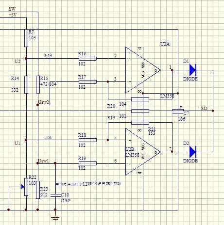
Control circuit adopts integrated circuit pulse width modulation chip SG3524. SG3524 connect with sine function generator core ICL8038 to generate SPWM wave and to control full-bridge inverter circuit. According SG3524 working principle, to get SPWM wave, must be a sine wave, it will be added to the SG3524 internal and compared with the sawtooth, sinusoidal pulse width modulation wave can be obtained.
Figure 5 shows a sine wave voltage is generated by the function generator ICL8038. Sine wave frequency is determined by R2, R3 and C1, 1.15/(R2+R3)C1, in order to facilitate debugging, we make R2, R3 are adjustable resistance, R1 is used to adjust the degree of distortion sine wave. Then f=50Hz, R2+R3=10kΩ, where C1=2. 2uF. After the sine wave PWM signal ue generating input to SG3524 foot No. 1, sine wave and sawtooth compares in SG3524 internal comparator to generate SPWM waves.

III. Summary
In this paper, the main achievement of the three-phase PWM inverter is main circuit design, including the rectifier circuit, filter circuit, an inverter, a drive circuit and a control circuit design, completed the selection of the relevant device, the basic realization of AC-DC-AC conversion function.
With the rapid economic development and energy supply tensions, development and utilization of electrical energy is more important. Currently, the world is making great efforts to develop new energy sources such as solar power, wind power, tidal power generation. In general, these new DC output generation means unstable, not directly to the needs of alternating current users. To do this, we need to convert direct current into alternating current, when necessary it can be incorporated into the utility grid. This DC-AC inverter technology needed to complete by the transformation. Therefore, the inverter technology in the new energy field of development and utilization has an important position.
I. Pulse width modulation inverter technology
1. PWM fundamentals
- a). Pulse width modulation inverter circuit Definition: to control the output voltage by changing the pulse width, to control the output frequency of the circuit by changing the modulation cycle.
- b). Pulse width modulation classification: 1. To modulate the pulse polarity can be divided into unipolar and bipolar modulation two kinds; 2. To the carrier frequency signal and the reference signal relationship between the frequency can be divided into two kinds of asynchronous and synchronous modulation.
- c). PWM inverter circuit features: you can get quite close to the sine wave output voltage and current, it is also known sinusoidal pulse width modulation SPWM (Sinusoidal PWM).
- d). SPWM control: that is to control the inverter circuit switching device on and off so that the output to give a series of equal amplitude and pulse width ranging, from using these pulses to instead of sinusoidal waveform required. According to certain rules of each pulse width modulated, it can change the size of the output voltage of the inverter circuit and the output frequency may also be varied.
- a). Carrier ratio is defined: In the 3-phase PWM power inverter circuit, the ratio of the carrier frequency fc and the modulated signal fr called the carrier frequency ratio, that is, N=fc/fr.
- b). 3-phase PWM inverter circuit control mode: According to whether the carrier wave and the modulation signal are synchronized has asynchronous and synchronous modulation two control mode. Asynchronous modulation control: When the entire carrier ratio is not a multiple of 3, carrier wave with the modulation signal is not synchronized modulation. Synchronous modulation control: In the three-phase inverter circuit when the carrier ratio is an integer multiple of 3, the carrier modulation signal modulation wave can be synchronized.
This power inverter design uses AC-DC-AC program, using SPWM modulation. Figure 1 is a block diagram of the main circuit and control circuit system. AC input voltage through the uncontrolled rectifier to get a DC voltage, and then get through the full-bridge inverter circuit output AC voltage. In order to ensure reliable operation of the main circuit to prevent interference of the control circuit, the use of main and control circuit is completely isolated from the method in which the driving signal optocoupler isolation, the feedback signal is isolated by transformers, auxiliary power is isolated by transformers.
1. Rectifier circuit design
The design uses a three-phase bridge uncontrolled rectifier circuit. In the AC-DC-AC inverter, uninterruptible power supplies, switching power supply applications, the most used uncontrolled rectifier circuit after capacitor filter provides direct power supply for the power-amp converter, inverter and other uses. Since the circuit power electronic devices are rectifier diodes, it is also known circuit such as a diode rectifier circuit. This circuit is as follows:
Calculated diode should be selected HFA70NH60 rated voltage 600V, rated current 70A (fast recovery type).
2. Power inverter circuit design
The inverter is corresponding with the rectifier to convert direct current into alternating current. AC flanked grid is active inverter. AC flanked load is passive inverter. The inverter design circuit adopts voltage three-phase bridge inverter circuit, its schematic diagram shown in figure 3.
Inverter circuit switching devices are made of full-controlled device IGBT. IGBT is a MOSFET and GTR composite device, so it has work fast, big input impedance, simple driving circuit, simple control circuit, higher operating frequency, large element capacity and many other advantages.
The design selected for the rated voltage of IGBT is 600V, rated current is about 20A, and therefore we should select six 600V, 20A IGBT tube. IGBT tube Model: IRGBC40F rated voltage 600V, rated current 27A. 6 diode has the effect of limiting overvoltage to protect IGBT tubes in power inverter circuit. Since voltage and current of the diode and IGBT tube are almost equal. So we select the diode model: HFA 70NH60 rated voltage 600V, rated current 70A (fast recovery type).
3. Output filter circuit design
The general form of the LC filter composed of LC passive network, its working principle is under the fundamental frequency series LC circuit series resonance state. In an ideal state, no fundamental voltage drop, high harmonic impedance is high, the effect of high harmonic currents. Calculated, take inductance value: L2=0. 48mH take capacitor capacitance value: C2=664uF.
4. 3-phase power inverter Driving circuit design
Driving circuit to isolate and amplify the control circuit generates a PWM signal. forming the driver circuit of each switching device switching signals. It logic level control circuit can drive 6 IGBT high/low- side switching circuit connection. Since the selection of drive circuit varies the switching device, but the subject selected switching device is IGBT, it is a voltage-driven switching device, so we chose the models IR2130 6-way fast IGBT driver chips produced by the US IR (International Rectifier).
IR2130 external circuit diagram shown in Figure 4, in the figure C25 is power supply filter capacitor, C24 is overcurrent detection capacitance, its size directly affects the protection sensitivity, to choose incorrectly can cause IGBT damage out of the safe operating area. C21, C22, C23 is the inverter bridge arm levitation power bootstrap capacitor, which affect the normal operation of these three power tubes. R27~R30, P2 are overcurrent detection resistor, you take the current protection value adjustable size just change the size of P2. R21~R26 are the IGBT gate resistor. D1~D6 selected fast recovery diodes.
5. 3-phase PWM power inverter Control Circuit Design
Control circuit adopts integrated circuit pulse width modulation chip SG3524. SG3524 connect with sine function generator core ICL8038 to generate SPWM wave and to control full-bridge inverter circuit. According SG3524 working principle, to get SPWM wave, must be a sine wave, it will be added to the SG3524 internal and compared with the sawtooth, sinusoidal pulse width modulation wave can be obtained.
Figure 5 shows a sine wave voltage is generated by the function generator ICL8038. Sine wave frequency is determined by R2, R3 and C1, 1.15/(R2+R3)C1, in order to facilitate debugging, we make R2, R3 are adjustable resistance, R1 is used to adjust the degree of distortion sine wave. Then f=50Hz, R2+R3=10kΩ, where C1=2. 2uF. After the sine wave PWM signal ue generating input to SG3524 foot No. 1, sine wave and sawtooth compares in SG3524 internal comparator to generate SPWM waves.
III. Summary
In this paper, the main achievement of the three-phase PWM inverter is main circuit design, including the rectifier circuit, filter circuit, an inverter, a drive circuit and a control circuit design, completed the selection of the relevant device, the basic realization of AC-DC-AC conversion function.
Post a Comment:
You may also like:

Power Inverter Source
Featured Articles
How to Choose a Suitable Power ...
 How to select the inverter for an air conditioner, television, computer or the motor? How to match the battery? How long is the ...
How to select the inverter for an air conditioner, television, computer or the motor? How to match the battery? How long is the ...12V 300W Uni-polar Isolation Pure Sine ...
 12v 300w uni-polar isolation of pure sine wave inverter Basic parameters Nominal power: 300W; continuous power: 250W; Peak power: ...
12v 300w uni-polar isolation of pure sine wave inverter Basic parameters Nominal power: 300W; continuous power: 250W; Peak power: ...600w Pure Sine Wave Power Inverter ...
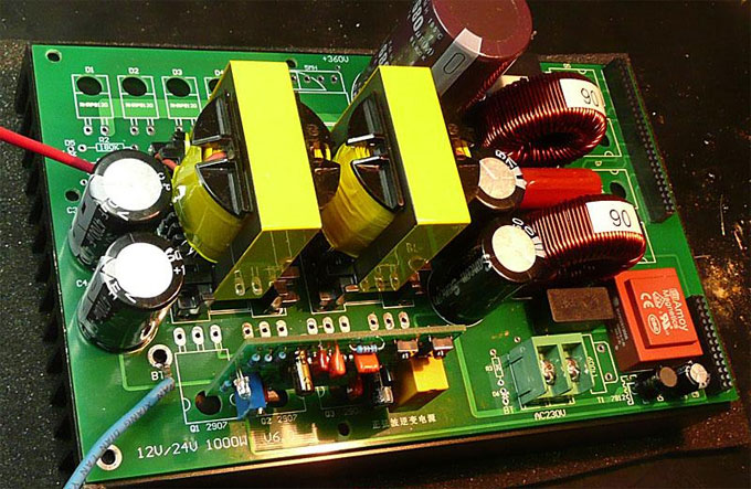
 I spent nearly a month design a 600w pure sine wave power inverter. The machine has the following characteristics: 1. SPWM drive ...
I spent nearly a month design a 600w pure sine wave power inverter. The machine has the following characteristics: 1. SPWM drive ...1000w 12V DC Home Power Inverter ...
 This power inverter is designed for 12v DC, but also can be connected to 24v DC, my goal is 800 watt, strive to 1000 watt pure ...
This power inverter is designed for 12v DC, but also can be connected to 24v DC, my goal is 800 watt, strive to 1000 watt pure ...