1500W Power Inverter Circuit Design
This is a full set of 12V/1500W power inverter. This is a single-sided PCB with straight pin elements. Because now is very hard to get so many specifications of the element, since a 0805 resistor is 5K, buy a hardly used up, so I installed straight pin elements. And for a lot of people, they can do on their own with a thermal transfer with the one-side PCB.
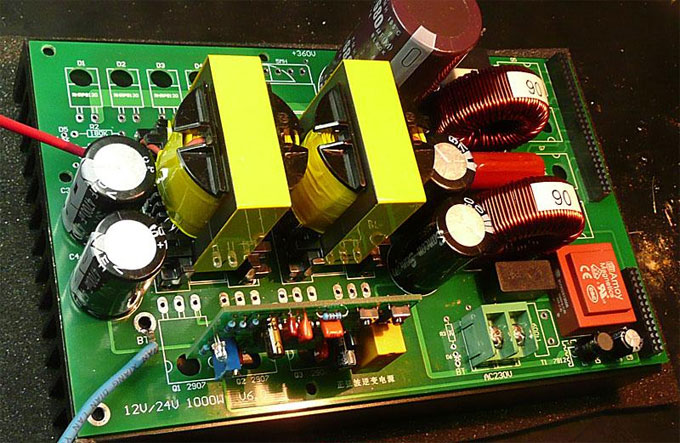
The main change of the 1500 watt power inverter is the 12V input, I used the full input and output full isolation design, so a total of three transformer windings.
The following is a tube IRF1404 three pairs of work as part of the boost. I will be separated from the radiator to the best way of heat conduction heat treatment. My power supply is 12V 130A, the output AC power to 1100W when the radiator lukewarm, the fan is not used at the time.

7815 edge IRF3205 is doing reverse polarity protection, and it is directly connected to the radiator fixed manner, so that benefits are very easy to install, the negative electrode of the battery can also be a direct hit on the radiator fixed with screws manner than welding way more reliable and convenient. The top of the radiator there are two vacancies 4MM screws, the battery can be negative copper nose directly hit the top.
The U5 position can be entered on a machine with 24V. You need to install the U5 7812 to UC3525 power supply. This power inverter is a 12V input, so I direct the element short-circuited.
There are 4 high-voltage rectifier diodes, here I used RHRP8120. Do not use the pipe 1200V, waste and affect efficiency.
All the elements are very good find, and no special element, I try to make this is the most simple, with a minimum of components to achieve perfect function, because of the simple problem is not easy, but also easy to debug.
I also installed a 7815 regulator, designed to give the posterior pole of the power supply, before and after class from here separated. Two Y capacitors are used for electromagnetic radiation treatment, which is input to the noise reduction circuit. Ensure that there is a very low noise radiation on the radiator. After the pole have a separate, connected to the chassis to ground.
Below is a sampling circuit of high voltage isolation, is still a classic circuit PC817+TL431, some people may ask, high voltage is generally very high, more than TL431 voltage of 36V, and is how to get this circuit is actually using a separate supply power to the PC817 and the TL431 solve, because I posterior pole from all over the 15V voltage, so the power supply directly from 7815 regulator over. Which will made PCB routing more convenient.

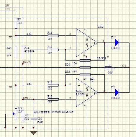
LM324 protection circuit caused me great trouble, because I used the LM324 chip, the chip itself may have many questions. I use it for comparison, a complete four functions, input under-voltage protection, input over-voltage protection, output over-current protection and temperature controlling fan, corresponding internal four op amps.
In a part of the H-bridge inverter MOSFET, I used the FQA28N50 pipe. Since the H-bridge can be seen as a combination of two half-bridge, half-bridge, so I have every parallel a 400V/105 of CBB capacitor. This is very important, since you can remove a lot of worries.
AC1, AC2 terminal is the output inductor each AC 220V terminals of the LC filter composed of two large inductance, Inductance with an outer diameter of 90 permeability sendust inductance 39.9mm around 110 laps to do, about 1.5MH.
The edge of the small common mode inductance, the volume is relatively small. This specification is 3MH, with the 1.0 of the wound, if we find the right, then with an outer diameter of about 18mm, height of 8mm high magnetic. This magnetic ring is usually green, as more than 10 laps to each side around. If you cannot find one, a direct link can also do the job.
The edge 502 is 5K potentiometer resistance is used to adjust the current protection threshold. It will also be able to adjust the output power of a member. It is not a very reliable component, so I set aside a fixed resistance interface on the PCB. Under normal circumstances, it will be replaced by a fixed resistor, this current protection threshold is fixed, it will not because the potentiometer failure caused by the failure of current protection.
PE terminal inserts for housing and connected directly to the power inverter ground. According to some other criteria, such as safety regulations on the appliance, this approach is not reliable. This is soldered directly to the PCB need only reliable way. I did not use, but with a simple way to do this is to facilitate the production.
LED interface is used done under-voltage indication, as long as the corresponding fitted with red and green LED can be done to protect both, and may indicate the purpose. If this port is not connected, the over and under-voltage protections will be cancelled.
FAN interface is used to access the fan. The TIP122 edge is to control fan switch. The two jacks are the same, so you can take two fans for the 1500w power inverter. Supply voltage is the input voltage range, negative right definition of the left.

The main change of the 1500 watt power inverter is the 12V input, I used the full input and output full isolation design, so a total of three transformer windings.
The following is a tube IRF1404 three pairs of work as part of the boost. I will be separated from the radiator to the best way of heat conduction heat treatment. My power supply is 12V 130A, the output AC power to 1100W when the radiator lukewarm, the fan is not used at the time.
7815 edge IRF3205 is doing reverse polarity protection, and it is directly connected to the radiator fixed manner, so that benefits are very easy to install, the negative electrode of the battery can also be a direct hit on the radiator fixed with screws manner than welding way more reliable and convenient. The top of the radiator there are two vacancies 4MM screws, the battery can be negative copper nose directly hit the top.
The U5 position can be entered on a machine with 24V. You need to install the U5 7812 to UC3525 power supply. This power inverter is a 12V input, so I direct the element short-circuited.
There are 4 high-voltage rectifier diodes, here I used RHRP8120. Do not use the pipe 1200V, waste and affect efficiency.
All the elements are very good find, and no special element, I try to make this is the most simple, with a minimum of components to achieve perfect function, because of the simple problem is not easy, but also easy to debug.
I also installed a 7815 regulator, designed to give the posterior pole of the power supply, before and after class from here separated. Two Y capacitors are used for electromagnetic radiation treatment, which is input to the noise reduction circuit. Ensure that there is a very low noise radiation on the radiator. After the pole have a separate, connected to the chassis to ground.
Below is a sampling circuit of high voltage isolation, is still a classic circuit PC817+TL431, some people may ask, high voltage is generally very high, more than TL431 voltage of 36V, and is how to get this circuit is actually using a separate supply power to the PC817 and the TL431 solve, because I posterior pole from all over the 15V voltage, so the power supply directly from 7815 regulator over. Which will made PCB routing more convenient.
LM324 protection circuit caused me great trouble, because I used the LM324 chip, the chip itself may have many questions. I use it for comparison, a complete four functions, input under-voltage protection, input over-voltage protection, output over-current protection and temperature controlling fan, corresponding internal four op amps.
In a part of the H-bridge inverter MOSFET, I used the FQA28N50 pipe. Since the H-bridge can be seen as a combination of two half-bridge, half-bridge, so I have every parallel a 400V/105 of CBB capacitor. This is very important, since you can remove a lot of worries.
AC1, AC2 terminal is the output inductor each AC 220V terminals of the LC filter composed of two large inductance, Inductance with an outer diameter of 90 permeability sendust inductance 39.9mm around 110 laps to do, about 1.5MH.
The edge of the small common mode inductance, the volume is relatively small. This specification is 3MH, with the 1.0 of the wound, if we find the right, then with an outer diameter of about 18mm, height of 8mm high magnetic. This magnetic ring is usually green, as more than 10 laps to each side around. If you cannot find one, a direct link can also do the job.
The edge 502 is 5K potentiometer resistance is used to adjust the current protection threshold. It will also be able to adjust the output power of a member. It is not a very reliable component, so I set aside a fixed resistance interface on the PCB. Under normal circumstances, it will be replaced by a fixed resistor, this current protection threshold is fixed, it will not because the potentiometer failure caused by the failure of current protection.
PE terminal inserts for housing and connected directly to the power inverter ground. According to some other criteria, such as safety regulations on the appliance, this approach is not reliable. This is soldered directly to the PCB need only reliable way. I did not use, but with a simple way to do this is to facilitate the production.
LED interface is used done under-voltage indication, as long as the corresponding fitted with red and green LED can be done to protect both, and may indicate the purpose. If this port is not connected, the over and under-voltage protections will be cancelled.
FAN interface is used to access the fan. The TIP122 edge is to control fan switch. The two jacks are the same, so you can take two fans for the 1500w power inverter. Supply voltage is the input voltage range, negative right definition of the left.
Post a Comment:
You may also like:

Power Inverter Source
Featured Articles
How to Choose a Suitable Power ...
How to select the inverter for an air conditioner, television, computer or the motor? How to match the battery? How long is the ...
How to select the inverter for an air conditioner, television, computer or the motor? How to match the battery? How long is the ...12V 300W Uni-polar Isolation Pure Sine ...
 12v 300w uni-polar isolation of pure sine wave inverter Basic parameters Nominal power: 300W; continuous power: 250W; Peak power: ...
12v 300w uni-polar isolation of pure sine wave inverter Basic parameters Nominal power: 300W; continuous power: 250W; Peak power: ...600w Pure Sine Wave Power Inverter ...
 I spent nearly a month design a 600w pure sine wave power inverter. The machine has the following characteristics: 1. SPWM drive ...
I spent nearly a month design a 600w pure sine wave power inverter. The machine has the following characteristics: 1. SPWM drive ...1000w 12V DC Home Power Inverter ...
 This power inverter is designed for 12v DC, but also can be connected to 24v DC, my goal is 800 watt, strive to 1000 watt pure ...
This power inverter is designed for 12v DC, but also can be connected to 24v DC, my goal is 800 watt, strive to 1000 watt pure ...