Home » Car Power Inverter » 300W Car Inverter Circuit Introduction
300W Car Inverter Circuit Introduction
300 w car inverter indicators:
Input voltage: DC 10V~14.5V
Output voltage: AC 200V~220V±10%
Output frequency: 50Hz±5%
Output Power: 70W~150W
Conversion efficiency: Higher than 85%
Inverter operating frequency: 30kHz~50kHz
300 watt car inverter circuit and working principle
Currently on the market sales of the largest, the most common car inverter output power of 70W-150W, the inverter circuit mainly uses TL494 or KA7500 chip-based pulse width modulation circuit.
The entire car inverter circuit-board can be divided into two parts, each part applied a TL494 or KA7500 chip control circuit composition, wherein the action of the first part of the circuit is 12V DC car battery, etc. Power will be provided by high-frequency PWM (pulse width modulation). Switching power supply technology is converted into 30kHz-50kHz, AC 220V. The role of the second part of the circuit is to use the bridge rectifier, filter, pulse-width modulation and switching power output and other technologies, the 30kHz~50kHz, 220V alternating current into an alternating current of about 50Hz.
Car inverter circuit introduction
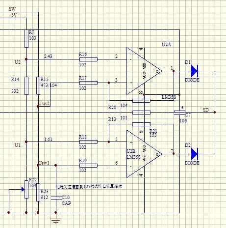
The circuit is consist by chip IC1 and its peripheral circuits, transistors VT1, VT3, MOS power transistor VT2, VT4 and transformer T1, 12V-DC converter of 220V/50kHz AC inverter circuit. By the chip IC2 and its peripheral circuits, transistors VT5, VT8, MOS power transistor VT6, VT7, VT9, VT10 and 220V/50kHz rectifier, filter circuit VD5-VD8, C12 common components 220V/50kHz high-frequency alternating current is converted to 220V/50Hz AC frequency conversion circuit, the final output by XAC outlet 220V/50Hz AC for a variety of portable electrical appliances.
IC1, IC2 using TL494CN (or KA7500C) chip, constitute the core automotive inverter control circuit. TL494CN is a dedicated two-terminal type switching power supply control chip, the suffix letter represents CN chip package outline dual in-line plastic structure, operating temperature range is 0℃-70℃, the limit supply voltage of 7V~40V, maximum operating frequency is 300kHz. TL494 chip built-in 5V reference source, voltage regulator accuracy of 5V±5%, load capacity of 10mA, and through its 14-pin output for external circuits. TL494 device also includes two NPN power output tubes can provide drive capability of 500mA.
In the circuit, R1 15 feet of peripheral circuits IC1, C1 composition of the power soft-start circuitry. When the voltage across capacitor C1 is gradually increased from 0V, only when the voltage across C1 reaches 5V or more, allowed IC1 internal pulse width modulator circuit starts operating. When the power is off, C1 discharges through resistor R2 to ensure the soft-start circuit to work on the next power-up.
R1 IC1 15-pin peripheral circuit, Rt, R2 composed of the thermal protection circuit. Rt is a positive temperature coefficient thermistor, the resistance at room temperature may be optionally within the range of 150Ω~300Ω appropriately selected from higher to improve thermal protection circuit is activated sensitivity.
Thermistor Rt during installation to close to the MOS power switch on VT2 or VT4 metal fins, so as to ensure effective thermal protection circuit.
IC1 15 feet to the ground voltage value U is a more important parameter. Circuit U≈Vcc×R2/(R1 + Rt + R2)V, calculated at normal temperature is U≈6.2V. Found that the requirements under normal operating conditions IC1 15 pin voltage should be slightly higher than the 16-pin voltage (14-pin chip is connected to 5V), which at room temperature 6.2V voltage value of the right size to meet the requirements and to leave a margin slightly.
When the circuit is not working, MOS power transistor VT2 or VT4 rise substantially increase the resistance of the thermistor Rt exceeds about 4kΩ, the output of IC1 internal comparator 1 will be low rollover is high, 3 feet of IC1 flip also went to a high state, causing the chip internal PWM comparator, ‘or’ gates and ‘nor’ gate outputs are toggling the output stage transistors VT1 and VT2 transistors are turned off. When two power output of IC1 inner tube off, the circuit VT1, VT3 base is extremely low due to the saturated conduction, VT1, after VT3 conduction. The power transistor VT2 and VT4 gate because no positive bias and in the off state, the inverter circuit to stop working.
VDZ1 1 foot of peripheral circuits IC1, R5, VD1, C2, R6 constituting the 12V input supply overvoltage protection circuit. The Zener voltage VDZ1 determine the starting gate protection circuit threshold voltage value, VD1, C2, R6 also formed sustain circuit protection status, as long as the instantaneous input supply overvoltage phenomenon. The protection circuit will start and continue for some time to ensure security in the post-stage power output tube. Considering the magnitude of normal changes in cars during battery voltage, typically VDZ1 Zener voltage of 15V or 16V selected as more appropriate.
C3 IC1 3 feet peripheral circuits, R5 constitute a power soft-start time maintaining circuit protection and maintain critical state circuit. It is in fact start control circuit soft-start control or protection circuit, which are reflected in the final result IC1 3 feet on the state level. When the circuit is working or the protection circuit is activated, IC1 3 feet will be high. When IC1 3 feet is high, it will charge the capacitor C3. This results in protection circuit is activated incentive disappears, C3 through R5 discharged by the discharge time is required, so that the protective state of the circuit is still maintained for some time.
When IC1's 3 feet high, will be along the R8, VD4 capacitor C7 is charged while the voltage across the capacitor C7 to the IC2 of 4 feet, 4 feet of IC2 held high state. From chip circuit of Figure 2, when 4 feet high, will raise chip dead time comparator noninverting input potential, so that the comparator output remains at a constant high level, the ‘or’ gate and ‘nor’ gate after the built-in transistor VT1 and VT2 are turned off. The circuit of Figure 1 VT5 and VT8 are in saturated conduction state. The subsequent stage MOS transistor VT6 and VT9 will vary no positive gate bias is in the OFF state, the inverter circuit to stop working.
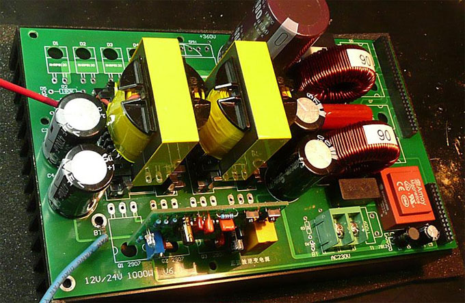
Pulse-width modulation frequency IC1 5 feet external capacitor C4 (472) and a 6-pin external resistor R7 (4k3) is a timing element pulse width modulator, the decision is fosc=1.1÷(0.0047×4.3) kHz≈50kHz. That circuit transistor VT1, VT2, VT3, VT4, the operating frequency of the transformer T1 are around 50kHz, so the T1 should use high-frequency ferrite core transformer. The transformer T1 role is to boost 12V to 220V pulse its primary turns is 20×2, secondary turns is 380.
IC2 5 feet external capacitor C8 (104) and a 6-pin external resistor R14 (220k) for the pulse width are modulator timing components. Pulse width modulation frequency is determined by fosc=1.1÷ (C8×R14)=1.1÷(0.1×220)kHz≈50Hz.
R29, R30, R27, C11, VDZ2 composition XAC outlet 220V output of the overvoltage protection circuit. When the output voltage is too high will cause the regulator VDZ2 breakdown, the IC2 of 4 feet on the ground voltage rise protection within the chip IC2 circuit action, cut off the output.
Car inverter circuit MOS transistor VT2, VT4 has some power, you must install the heatsink, and other devices are not required to install the heat sink. When the car power inverter products continually applied in higher power occasions, small fan is needed to be installed to help dissipate heat.

Input voltage: DC 10V~14.5V
Output voltage: AC 200V~220V±10%
Output frequency: 50Hz±5%
Output Power: 70W~150W
Conversion efficiency: Higher than 85%
Inverter operating frequency: 30kHz~50kHz
300 watt car inverter circuit and working principle
Currently on the market sales of the largest, the most common car inverter output power of 70W-150W, the inverter circuit mainly uses TL494 or KA7500 chip-based pulse width modulation circuit.
The entire car inverter circuit-board can be divided into two parts, each part applied a TL494 or KA7500 chip control circuit composition, wherein the action of the first part of the circuit is 12V DC car battery, etc. Power will be provided by high-frequency PWM (pulse width modulation). Switching power supply technology is converted into 30kHz-50kHz, AC 220V. The role of the second part of the circuit is to use the bridge rectifier, filter, pulse-width modulation and switching power output and other technologies, the 30kHz~50kHz, 220V alternating current into an alternating current of about 50Hz.
Car inverter circuit introduction
The circuit is consist by chip IC1 and its peripheral circuits, transistors VT1, VT3, MOS power transistor VT2, VT4 and transformer T1, 12V-DC converter of 220V/50kHz AC inverter circuit. By the chip IC2 and its peripheral circuits, transistors VT5, VT8, MOS power transistor VT6, VT7, VT9, VT10 and 220V/50kHz rectifier, filter circuit VD5-VD8, C12 common components 220V/50kHz high-frequency alternating current is converted to 220V/50Hz AC frequency conversion circuit, the final output by XAC outlet 220V/50Hz AC for a variety of portable electrical appliances.
IC1, IC2 using TL494CN (or KA7500C) chip, constitute the core automotive inverter control circuit. TL494CN is a dedicated two-terminal type switching power supply control chip, the suffix letter represents CN chip package outline dual in-line plastic structure, operating temperature range is 0℃-70℃, the limit supply voltage of 7V~40V, maximum operating frequency is 300kHz. TL494 chip built-in 5V reference source, voltage regulator accuracy of 5V±5%, load capacity of 10mA, and through its 14-pin output for external circuits. TL494 device also includes two NPN power output tubes can provide drive capability of 500mA.
In the circuit, R1 15 feet of peripheral circuits IC1, C1 composition of the power soft-start circuitry. When the voltage across capacitor C1 is gradually increased from 0V, only when the voltage across C1 reaches 5V or more, allowed IC1 internal pulse width modulator circuit starts operating. When the power is off, C1 discharges through resistor R2 to ensure the soft-start circuit to work on the next power-up.
R1 IC1 15-pin peripheral circuit, Rt, R2 composed of the thermal protection circuit. Rt is a positive temperature coefficient thermistor, the resistance at room temperature may be optionally within the range of 150Ω~300Ω appropriately selected from higher to improve thermal protection circuit is activated sensitivity.
Thermistor Rt during installation to close to the MOS power switch on VT2 or VT4 metal fins, so as to ensure effective thermal protection circuit.
IC1 15 feet to the ground voltage value U is a more important parameter. Circuit U≈Vcc×R2/(R1 + Rt + R2)V, calculated at normal temperature is U≈6.2V. Found that the requirements under normal operating conditions IC1 15 pin voltage should be slightly higher than the 16-pin voltage (14-pin chip is connected to 5V), which at room temperature 6.2V voltage value of the right size to meet the requirements and to leave a margin slightly.
When the circuit is not working, MOS power transistor VT2 or VT4 rise substantially increase the resistance of the thermistor Rt exceeds about 4kΩ, the output of IC1 internal comparator 1 will be low rollover is high, 3 feet of IC1 flip also went to a high state, causing the chip internal PWM comparator, ‘or’ gates and ‘nor’ gate outputs are toggling the output stage transistors VT1 and VT2 transistors are turned off. When two power output of IC1 inner tube off, the circuit VT1, VT3 base is extremely low due to the saturated conduction, VT1, after VT3 conduction. The power transistor VT2 and VT4 gate because no positive bias and in the off state, the inverter circuit to stop working.
VDZ1 1 foot of peripheral circuits IC1, R5, VD1, C2, R6 constituting the 12V input supply overvoltage protection circuit. The Zener voltage VDZ1 determine the starting gate protection circuit threshold voltage value, VD1, C2, R6 also formed sustain circuit protection status, as long as the instantaneous input supply overvoltage phenomenon. The protection circuit will start and continue for some time to ensure security in the post-stage power output tube. Considering the magnitude of normal changes in cars during battery voltage, typically VDZ1 Zener voltage of 15V or 16V selected as more appropriate.
C3 IC1 3 feet peripheral circuits, R5 constitute a power soft-start time maintaining circuit protection and maintain critical state circuit. It is in fact start control circuit soft-start control or protection circuit, which are reflected in the final result IC1 3 feet on the state level. When the circuit is working or the protection circuit is activated, IC1 3 feet will be high. When IC1 3 feet is high, it will charge the capacitor C3. This results in protection circuit is activated incentive disappears, C3 through R5 discharged by the discharge time is required, so that the protective state of the circuit is still maintained for some time.
When IC1's 3 feet high, will be along the R8, VD4 capacitor C7 is charged while the voltage across the capacitor C7 to the IC2 of 4 feet, 4 feet of IC2 held high state. From chip circuit of Figure 2, when 4 feet high, will raise chip dead time comparator noninverting input potential, so that the comparator output remains at a constant high level, the ‘or’ gate and ‘nor’ gate after the built-in transistor VT1 and VT2 are turned off. The circuit of Figure 1 VT5 and VT8 are in saturated conduction state. The subsequent stage MOS transistor VT6 and VT9 will vary no positive gate bias is in the OFF state, the inverter circuit to stop working.
Pulse-width modulation frequency IC1 5 feet external capacitor C4 (472) and a 6-pin external resistor R7 (4k3) is a timing element pulse width modulator, the decision is fosc=1.1÷(0.0047×4.3) kHz≈50kHz. That circuit transistor VT1, VT2, VT3, VT4, the operating frequency of the transformer T1 are around 50kHz, so the T1 should use high-frequency ferrite core transformer. The transformer T1 role is to boost 12V to 220V pulse its primary turns is 20×2, secondary turns is 380.
IC2 5 feet external capacitor C8 (104) and a 6-pin external resistor R14 (220k) for the pulse width are modulator timing components. Pulse width modulation frequency is determined by fosc=1.1÷ (C8×R14)=1.1÷(0.1×220)kHz≈50Hz.
R29, R30, R27, C11, VDZ2 composition XAC outlet 220V output of the overvoltage protection circuit. When the output voltage is too high will cause the regulator VDZ2 breakdown, the IC2 of 4 feet on the ground voltage rise protection within the chip IC2 circuit action, cut off the output.
Car inverter circuit MOS transistor VT2, VT4 has some power, you must install the heatsink, and other devices are not required to install the heat sink. When the car power inverter products continually applied in higher power occasions, small fan is needed to be installed to help dissipate heat.
Post a Comment:
You may also like:

Power Inverter Source
Featured Articles
How to Choose a Suitable Power ...
 How to select the inverter for an air conditioner, television, computer or the motor? How to match the battery? How long is the ...
How to select the inverter for an air conditioner, television, computer or the motor? How to match the battery? How long is the ...12V 300W Uni-polar Isolation Pure Sine ...
 12v 300w uni-polar isolation of pure sine wave inverter Basic parameters Nominal power: 300W; continuous power: 250W; Peak power: ...
12v 300w uni-polar isolation of pure sine wave inverter Basic parameters Nominal power: 300W; continuous power: 250W; Peak power: ...600w Pure Sine Wave Power Inverter ...
 I spent nearly a month design a 600w pure sine wave power inverter. The machine has the following characteristics: 1. SPWM drive ...
I spent nearly a month design a 600w pure sine wave power inverter. The machine has the following characteristics: 1. SPWM drive ...1000w 12V DC Home Power Inverter ...
 This power inverter is designed for 12v DC, but also can be connected to 24v DC, my goal is 800 watt, strive to 1000 watt pure ...
This power inverter is designed for 12v DC, but also can be connected to 24v DC, my goal is 800 watt, strive to 1000 watt pure ...
please where is the schematic ?