Home » Working Principle » 500W Sine Wave Inverter Processing Guide
500W Sine Wave Inverter Processing Guide
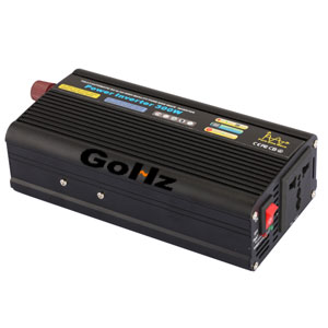
We bring you today is a 500W sine wave inverter production.
I have made inverters with over 1000 watt power, but the production process will encounter many problems. If not property processed, the device will roar like thunder. Not suitable for beginners, or is not associated instrumentation people to DIY. This time I made a new version, and strive to achieve the simplest, most practical, smallest, and has outstanding load capacity and other characteristics.
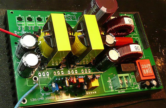
Below is the photo of the entire sine wave inverter. In order to save time, I used the board and the control board separate ways to do so that all the benefits of centralized control functions on a small board processing, large load board power conversion and transmission. This will greatly reduce the occurrence of interference and improve stability.

The control board as shown below, the board has a lot of components. So I used a double-sided PCB.
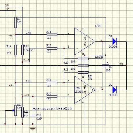
Pre-boost is also installed in the panel, using the TL494 plus boost the totem pole; stage SPWM chip or the use of TDS2285 chip, with CD4069+CD4081 TLP250 optocoupler output to drive the H-bridge. Power bootstrap powered driving. As long as the entire board +12V power to complete all the features.
In order to improve the stability and reliability, adding a variety of protection functions: over-voltage protection, under-voltage protection, thermal protection, short circuit protection and over-current protection.
The machine PCB circuit SCH document and the following documents:

First: Use a 0.75 on the wound 32T, evenly distributed in the skeleton inside.
Second: I use 2 0.3*25mm copper with two superimposed around 2+2.
Third: Primary remaining around the end 32T.
1. As long as the transformer winding up the primary symmetry, and there would be no problem. Because here, we used essentially in open loop.
2. High-voltage rectifier diode: This machine is designed to work within the maximum range of 500W, the power is too low. So I use HER508 to do the actual discovery. Under full power operation, the diode is still a little hot, but a few hours of continuous work under the fan turned on, conditions are not bad. So it goes with no problem.
3. For pre-boost MOSFET, I selected 80V/110A NCE80H11. I could have been ready with a sharp Jun semiconductor RU6099, RU6099 before I have tested, the performance is very good, but I do Without this MOS material, and so we used NCE80H11.
4. H-bridge MOSFET, I use IRFB11N50APBF. The MOS performance is very good, often in the case of short-circuit, much higher than the life expectancy similar IRFP460, current is also smaller than the IRFP460. It is just right to use in the 500W device.
5. AC filter inductor, I use a relatively small magnetic ring with outer diameter of 27.5mm, height 14mm sendust ring, permeability 125u. I'm on top of the wound with two 0.55 for about 70 laps, large inductance of about 0.75MH. As a result of two such inductors, inductance therefore does not require a very large and can get very good filtering effect.
Assembly instructions:
1. First jumper on the motherboard to each weld, pay attention to the bottom of the transformer near C2 capacitive position has two slots. This is used to weld the jumper. I used a small copper welding up, you can also use a few jumper welded. Most jumpers are below the radiator, because the board did not mark the jumper label, so it is necessary to find and carefully soldered, or so the radiator is installed. The jumper was found less loaded trouble.
2. After which all components are installed it, then you can install the radiator. Install the heat sink cannot be short-circuited jumper, can cushion a little something below, I was under the mat insulation pad.
3. Finally install the panel, there is a control board to the H-bridge driver power supply pins, since this does not provide an interface on the motherboard, so the back of the control board will advance to the feet and +12V connected. As follows:

After these tasks are completed, as long as no wrong element, no welding position error, the sine wave inverter can work normally.
As can be seen from the full range of changes to the output load is small, only an AC cycle to stabilize the output can be seen TDS2285 chip regulator performance is still very good.
I have made inverters with over 1000 watt power, but the production process will encounter many problems. If not property processed, the device will roar like thunder. Not suitable for beginners, or is not associated instrumentation people to DIY. This time I made a new version, and strive to achieve the simplest, most practical, smallest, and has outstanding load capacity and other characteristics.
Below is the photo of the entire sine wave inverter. In order to save time, I used the board and the control board separate ways to do so that all the benefits of centralized control functions on a small board processing, large load board power conversion and transmission. This will greatly reduce the occurrence of interference and improve stability.
The control board as shown below, the board has a lot of components. So I used a double-sided PCB.
Pre-boost is also installed in the panel, using the TL494 plus boost the totem pole; stage SPWM chip or the use of TDS2285 chip, with CD4069+CD4081 TLP250 optocoupler output to drive the H-bridge. Power bootstrap powered driving. As long as the entire board +12V power to complete all the features.
In order to improve the stability and reliability, adding a variety of protection functions: over-voltage protection, under-voltage protection, thermal protection, short circuit protection and over-current protection.
The machine PCB circuit SCH document and the following documents:
First: Use a 0.75 on the wound 32T, evenly distributed in the skeleton inside.
Second: I use 2 0.3*25mm copper with two superimposed around 2+2.
Third: Primary remaining around the end 32T.
1. As long as the transformer winding up the primary symmetry, and there would be no problem. Because here, we used essentially in open loop.
2. High-voltage rectifier diode: This machine is designed to work within the maximum range of 500W, the power is too low. So I use HER508 to do the actual discovery. Under full power operation, the diode is still a little hot, but a few hours of continuous work under the fan turned on, conditions are not bad. So it goes with no problem.
3. For pre-boost MOSFET, I selected 80V/110A NCE80H11. I could have been ready with a sharp Jun semiconductor RU6099, RU6099 before I have tested, the performance is very good, but I do Without this MOS material, and so we used NCE80H11.
4. H-bridge MOSFET, I use IRFB11N50APBF. The MOS performance is very good, often in the case of short-circuit, much higher than the life expectancy similar IRFP460, current is also smaller than the IRFP460. It is just right to use in the 500W device.
5. AC filter inductor, I use a relatively small magnetic ring with outer diameter of 27.5mm, height 14mm sendust ring, permeability 125u. I'm on top of the wound with two 0.55 for about 70 laps, large inductance of about 0.75MH. As a result of two such inductors, inductance therefore does not require a very large and can get very good filtering effect.
Assembly instructions:
1. First jumper on the motherboard to each weld, pay attention to the bottom of the transformer near C2 capacitive position has two slots. This is used to weld the jumper. I used a small copper welding up, you can also use a few jumper welded. Most jumpers are below the radiator, because the board did not mark the jumper label, so it is necessary to find and carefully soldered, or so the radiator is installed. The jumper was found less loaded trouble.
2. After which all components are installed it, then you can install the radiator. Install the heat sink cannot be short-circuited jumper, can cushion a little something below, I was under the mat insulation pad.
3. Finally install the panel, there is a control board to the H-bridge driver power supply pins, since this does not provide an interface on the motherboard, so the back of the control board will advance to the feet and +12V connected. As follows:
After these tasks are completed, as long as no wrong element, no welding position error, the sine wave inverter can work normally.
As can be seen from the full range of changes to the output load is small, only an AC cycle to stabilize the output can be seen TDS2285 chip regulator performance is still very good.
how did you manage to give seperate vcc for tlp250 and hbridge circuit,please tell me ?
Post a Comment:
You may also like:

Power Inverter Source
Featured Articles
How to Choose a Suitable Power ...
 How to select the inverter for an air conditioner, television, computer or the motor? How to match the battery? How long is the ...
How to select the inverter for an air conditioner, television, computer or the motor? How to match the battery? How long is the ...12V 300W Uni-polar Isolation Pure Sine ...
 12v 300w uni-polar isolation of pure sine wave inverter Basic parameters Nominal power: 300W; continuous power: 250W; Peak power: ...
12v 300w uni-polar isolation of pure sine wave inverter Basic parameters Nominal power: 300W; continuous power: 250W; Peak power: ...600w Pure Sine Wave Power Inverter ...
 I spent nearly a month design a 600w pure sine wave power inverter. The machine has the following characteristics: 1. SPWM drive ...
I spent nearly a month design a 600w pure sine wave power inverter. The machine has the following characteristics: 1. SPWM drive ...1000w 12V DC Home Power Inverter ...
 This power inverter is designed for 12v DC, but also can be connected to 24v DC, my goal is 800 watt, strive to 1000 watt pure ...
This power inverter is designed for 12v DC, but also can be connected to 24v DC, my goal is 800 watt, strive to 1000 watt pure ...