Home » Car Power Inverter » 12V to 220V Homemade Car Inverter Detailed Annotation
12V to 220V Homemade Car Inverter Detailed Annotation
People may feel inconvenient when half-way car troubleshooting, when holding countryside picnic or recreational activities, and there are some areas without utility power supply. In some cases, people only can lengthen the cable to lead the main power. But, it is dangerous, impossible or impractical to do so. On these occasions, a car inverter will be very useful. It can invert 12V car battery into 220V AC power.
This article describes the car inverter main consists of the MOS field-effect tube and ordinary power transformer composition. The output power depends on the MOS FET and power source transformer, which eliminates the cumbersome transformer winding and is suitable for use in electronic amateur production. Here is the working principle of the transformer and the production process.
Inverter circuit and working principle: circuit is shown in figure 1. We will introduce the working principle of inverter in detail.

I.The generation of square wave
Here we use CD4069 to constitute the square-wave generator for the car inverter. R1 is a compensation resistor in the circuit, which is used for improving oscillation frequency instability caused by the changes of supply voltage. Circuit oscillation is performed by the capacitor C1 charging and discharging.
Oscillation frequency: f=1/2.2RC
Maximum frequency: fmax=1/2.2x103x2.2x10-6=62.6Hz
Minimum frequency: fmin=1/2.2x4.3x103x2.2x10-6=48.0Hz
Since the error of components, the actual value will be slightly different. Other excess generator, input is grounded to avoid affecting other circuits.

II. FET driving circuit
Since the oscillation signal voltage maximum amplitude of square wave signal generator output is 0~5V. In order to full drive the power switching circuit, here the oscillation signal voltages is amplified to 0~12V with TR1, TR2 of. As shown in figure 3.

III. FET power switching circuit
FET is the core of the car inverter. I will sketch the working process of the application circuit which consists of the C-MOS FET (as shown in figure 4). The circuit combined a P-channel and an N-channel enhancement mode MOS FET. When the input terminal is the low level, N-channel MOS FET is breakover, output terminal and the positive power supply is turned on. When the input is high, N-channel MOS FET output terminal and the power ground are turned on. In this circuit, P-channel MOS FET and N-channel field effect transistor always work in the opposite state, its phase of the input and output terminals is opposite. We can get a larger current output by this way of working. At the same time due to the leakage currents, so that MOS FET is turned off not in the gate voltage to 0V (typically less than 1V to 2V). Different FET turn-off voltage is slightly different. Because of this, the circuit will not cause the power supply circuit because two tube simultaneous conduction.

From the above analysis we can draw the working process of MOS FET section in the schematic diagram (as shown in figure 5).

Working principle like mentioned above, when this low voltage, high current, 50Hz frequency alternating signal through the low voltage winding of the transformer, it will induce high-voltage AC voltage in the high-voltage side of the transformer, DC to AC conversion is completed. It should be noted that, in some cases, for example, when part of the oscillation stop working, the low-voltage side of the transformer sometimes transits large current, so the fuse of the circuit can’t be omitted or shorted.
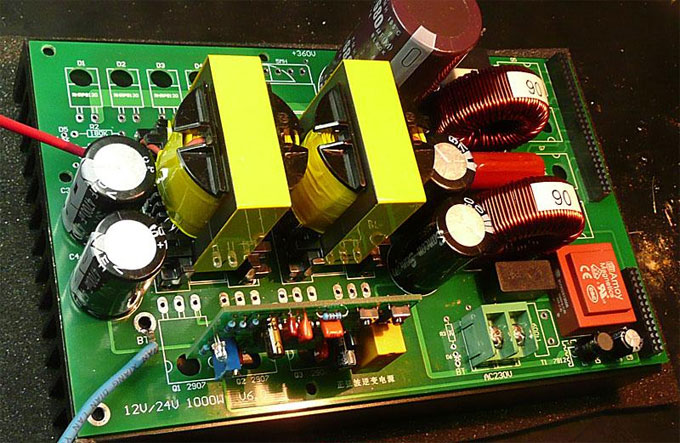
Circuit board is shown in figure 6. The used components reference to figure 7. Car inverter transformer is secondary voltage 12V, current 10A, the primary voltage 220V refined power transformer. P-channel MOS FET (2SJ471) maximum drain current is 30A. The resistance value between drain-source is 25 milliohms. At this point there is 2.5W power consumption if through a 10A current. N-channel MOS FET (2SK2956) maximum drain current is 50A, when the FET the resistance value between drain-source is 7 milliohms. At this point there is 0.7W power consumption if through a 10A current. From this we know that 2SJ471 heating is about 4 times the 2SK2956 in the case of the same operating current. So we should pay attention to this point when considering radiators. Figure 8 show inverter FET of the article describes Location distribution and connection in the radiator (100mm×100mm×17mm). FET heat will not be great in the state of work, but here we choice a little large radiator for security.


IV. Car Inverter Performance Testing
Here testing input power supply adopt the 12V car battery of low internal resistance, discharge current (typically greater than 100A), it can provide enough power for the input circuit. Test load is a normal light bulb. The test method is by changing the load size, and measured input current, voltage and output voltage at this time. The test results are shown in voltage, current curve relationship. It can be seen that the output voltage decreases with the increase of the load, the lamp power consumption changes with the change in voltage. We can also find out the relationship between the output voltage and power by calculating. But in fact due to the electric resistance of the bulb change will vary by the voltage applied to both ends, and the output voltage and current are not sine wave, so this calculation must be regarded as estimates. To load 60W bulb as an example: Suppose the resistance of the bulb does not change with the change in voltage. Because R=V2/W=2102/60=735Ω, so W=V2/R=2082/735=58.9W when voltage is 208V. Thereby we converted into a relationship between voltage and power. Through testing, we found that input current is 10A when the output power is about 100W. In this case the output voltage is 200V.
Figure 9 is a waveform diagram of the different output load for everyone to make reference.
Inverter products are finished by manufacturers as shown in figure 10.

This article describes the car inverter main consists of the MOS field-effect tube and ordinary power transformer composition. The output power depends on the MOS FET and power source transformer, which eliminates the cumbersome transformer winding and is suitable for use in electronic amateur production. Here is the working principle of the transformer and the production process.
Inverter circuit and working principle: circuit is shown in figure 1. We will introduce the working principle of inverter in detail.
I.The generation of square wave
Here we use CD4069 to constitute the square-wave generator for the car inverter. R1 is a compensation resistor in the circuit, which is used for improving oscillation frequency instability caused by the changes of supply voltage. Circuit oscillation is performed by the capacitor C1 charging and discharging.
Oscillation frequency: f=1/2.2RC
Maximum frequency: fmax=1/2.2x103x2.2x10-6=62.6Hz
Minimum frequency: fmin=1/2.2x4.3x103x2.2x10-6=48.0Hz
Since the error of components, the actual value will be slightly different. Other excess generator, input is grounded to avoid affecting other circuits.
II. FET driving circuit
Since the oscillation signal voltage maximum amplitude of square wave signal generator output is 0~5V. In order to full drive the power switching circuit, here the oscillation signal voltages is amplified to 0~12V with TR1, TR2 of. As shown in figure 3.
III. FET power switching circuit
FET is the core of the car inverter. I will sketch the working process of the application circuit which consists of the C-MOS FET (as shown in figure 4). The circuit combined a P-channel and an N-channel enhancement mode MOS FET. When the input terminal is the low level, N-channel MOS FET is breakover, output terminal and the positive power supply is turned on. When the input is high, N-channel MOS FET output terminal and the power ground are turned on. In this circuit, P-channel MOS FET and N-channel field effect transistor always work in the opposite state, its phase of the input and output terminals is opposite. We can get a larger current output by this way of working. At the same time due to the leakage currents, so that MOS FET is turned off not in the gate voltage to 0V (typically less than 1V to 2V). Different FET turn-off voltage is slightly different. Because of this, the circuit will not cause the power supply circuit because two tube simultaneous conduction.
From the above analysis we can draw the working process of MOS FET section in the schematic diagram (as shown in figure 5).
Working principle like mentioned above, when this low voltage, high current, 50Hz frequency alternating signal through the low voltage winding of the transformer, it will induce high-voltage AC voltage in the high-voltage side of the transformer, DC to AC conversion is completed. It should be noted that, in some cases, for example, when part of the oscillation stop working, the low-voltage side of the transformer sometimes transits large current, so the fuse of the circuit can’t be omitted or shorted.
Circuit board is shown in figure 6. The used components reference to figure 7. Car inverter transformer is secondary voltage 12V, current 10A, the primary voltage 220V refined power transformer. P-channel MOS FET (2SJ471) maximum drain current is 30A. The resistance value between drain-source is 25 milliohms. At this point there is 2.5W power consumption if through a 10A current. N-channel MOS FET (2SK2956) maximum drain current is 50A, when the FET the resistance value between drain-source is 7 milliohms. At this point there is 0.7W power consumption if through a 10A current. From this we know that 2SJ471 heating is about 4 times the 2SK2956 in the case of the same operating current. So we should pay attention to this point when considering radiators. Figure 8 show inverter FET of the article describes Location distribution and connection in the radiator (100mm×100mm×17mm). FET heat will not be great in the state of work, but here we choice a little large radiator for security.
IV. Car Inverter Performance Testing
Here testing input power supply adopt the 12V car battery of low internal resistance, discharge current (typically greater than 100A), it can provide enough power for the input circuit. Test load is a normal light bulb. The test method is by changing the load size, and measured input current, voltage and output voltage at this time. The test results are shown in voltage, current curve relationship. It can be seen that the output voltage decreases with the increase of the load, the lamp power consumption changes with the change in voltage. We can also find out the relationship between the output voltage and power by calculating. But in fact due to the electric resistance of the bulb change will vary by the voltage applied to both ends, and the output voltage and current are not sine wave, so this calculation must be regarded as estimates. To load 60W bulb as an example: Suppose the resistance of the bulb does not change with the change in voltage. Because R=V2/W=2102/60=735Ω, so W=V2/R=2082/735=58.9W when voltage is 208V. Thereby we converted into a relationship between voltage and power. Through testing, we found that input current is 10A when the output power is about 100W. In this case the output voltage is 200V.
Figure 9 is a waveform diagram of the different output load for everyone to make reference.
Inverter products are finished by manufacturers as shown in figure 10.
Post a Comment:
You may also like:

Power Inverter Source
Featured Articles
How to Choose a Suitable Power ...
 How to select the inverter for an air conditioner, television, computer or the motor? How to match the battery? How long is the ...
How to select the inverter for an air conditioner, television, computer or the motor? How to match the battery? How long is the ...12V 300W Uni-polar Isolation Pure Sine ...
 12v 300w uni-polar isolation of pure sine wave inverter Basic parameters Nominal power: 300W; continuous power: 250W; Peak power: ...
12v 300w uni-polar isolation of pure sine wave inverter Basic parameters Nominal power: 300W; continuous power: 250W; Peak power: ...600w Pure Sine Wave Power Inverter ...
 I spent nearly a month design a 600w pure sine wave power inverter. The machine has the following characteristics: 1. SPWM drive ...
I spent nearly a month design a 600w pure sine wave power inverter. The machine has the following characteristics: 1. SPWM drive ...1000w 12V DC Home Power Inverter ...
 This power inverter is designed for 12v DC, but also can be connected to 24v DC, my goal is 800 watt, strive to 1000 watt pure ...
This power inverter is designed for 12v DC, but also can be connected to 24v DC, my goal is 800 watt, strive to 1000 watt pure ...