Micro-grid Multi-inverter Parallel Operational Control Strategy
In the micro-grid parallel multi-inverter systems, due to differences in line impedance inverter output impedance and the common connection point, the application of traditional droop control method will lead to greater circulation between the inverter and power sharing accuracy compared low. In the analysis of multi-inverter parallel system of traditional droop control method and inverter output impedance of system performance based on virtual by introducing inductive impedance is proposed for multi-inverter parallel micro-grid voltage and current bicyclic droop control strategy. The introduction of a virtual impedance of the output impedance is only determined by the filter inductance value, reducing the influence of the inverter output resistor; consider the impact of the line impedance, the droop propose a new and improved control algorithm, by droop factor correction, weakening the line impedance parallel differences affect the flow of improved multi-inverter parallel performance. The simulation and experimental results show the correctness and effectiveness of the control strategy.
Micro-grids for distributed power for its effective use and flexible, intelligent control features, become the focus of many countries in the coming years power development strategy. Since most distributed micro-grid power required by the power grid inverter and nuanced, so the inverter stable parallel operation will greatly enhance the overall capacity and reliability of the micro-grid system.

At present, the inverter control strategy for parallel operation is generally a master-slave control and droop control method and other methods. Master-slave control law on the control lines interconnect needs, will limit the distance between the parallel distributed power, it may also introduce noise, and thus its application has some limitations. Droop control method is a non-contact technology independent control signal line, by drawing self-synchronizing synchronous generator and voltage droop to achieve inter-cell technology without parallel signal lines. It does not require interconnection between the signal line of the inverter, only to be collected for each output of the inverter, dependent on its internal control policies, you can synchronize the parallel multi-inverter, current sharing operation. Compared to other control mode, the droop control system can be made simple in structure, functional redundancy, installation and maintenance quick and easy system expansion, low cost, more reliable parallel operation.
In multi-inverter parallel operation, parallel control as a key technology droop control method, the rational design of its droop factor directly affects the inverter parallel average flow effects and dynamic response. Droop coefficient inverter output impedance and line impedance are closely related. Different voltage and current dual-loop control strategy, different inverter output impedance values obtained; different voltage levels of connection lines correspond to different impedance ratio, especially in the low-voltage micro-grid, the connecting line relative to other voltage level on the line impedance is high much more, the line is longer, the resistance value is high; due to the distributed power supply and common connection point near and far, and thus the connection impedance differences, leading to increased circulation inverters and power distribution is uneven. Hence, an improved droop control methods have been proposed. Document proposed based on virtual power droop control method, by the actual active and reactive power into virtual power, the traditional droop control law be amended. But it pointed out its shortcomings and proposed based on virtual frequency - voltage droop control method, but this method requires parallel inverters have the same conversion angle, difficult to achieve.
This article will first analyze the traditional droop control law and its limits, then the introduction of inductive impedance virtual presents a more suitable micro-grid inverter parallel voltage-current dual-loop control strategy, under conditions of frequency inverter output impedance of the filter inductor value only decisions; consider the impact of the line impedance, the traditional method is improved droop control, determine the relationship between the line sag resistance coefficient, presents a new and improved droop control algorithm, by correcting droop factor, reduce line impedance difference parallel flow influences. Finally, simulation and experimental verification effectiveness of the proposed control strategy.
Micro-grids for distributed power for its effective use and flexible, intelligent control features, become the focus of many countries in the coming years power development strategy. Since most distributed micro-grid power required by the power grid inverter and nuanced, so the inverter stable parallel operation will greatly enhance the overall capacity and reliability of the micro-grid system.
At present, the inverter control strategy for parallel operation is generally a master-slave control and droop control method and other methods. Master-slave control law on the control lines interconnect needs, will limit the distance between the parallel distributed power, it may also introduce noise, and thus its application has some limitations. Droop control method is a non-contact technology independent control signal line, by drawing self-synchronizing synchronous generator and voltage droop to achieve inter-cell technology without parallel signal lines. It does not require interconnection between the signal line of the inverter, only to be collected for each output of the inverter, dependent on its internal control policies, you can synchronize the parallel multi-inverter, current sharing operation. Compared to other control mode, the droop control system can be made simple in structure, functional redundancy, installation and maintenance quick and easy system expansion, low cost, more reliable parallel operation.
In multi-inverter parallel operation, parallel control as a key technology droop control method, the rational design of its droop factor directly affects the inverter parallel average flow effects and dynamic response. Droop coefficient inverter output impedance and line impedance are closely related. Different voltage and current dual-loop control strategy, different inverter output impedance values obtained; different voltage levels of connection lines correspond to different impedance ratio, especially in the low-voltage micro-grid, the connecting line relative to other voltage level on the line impedance is high much more, the line is longer, the resistance value is high; due to the distributed power supply and common connection point near and far, and thus the connection impedance differences, leading to increased circulation inverters and power distribution is uneven. Hence, an improved droop control methods have been proposed. Document proposed based on virtual power droop control method, by the actual active and reactive power into virtual power, the traditional droop control law be amended. But it pointed out its shortcomings and proposed based on virtual frequency - voltage droop control method, but this method requires parallel inverters have the same conversion angle, difficult to achieve.
This article will first analyze the traditional droop control law and its limits, then the introduction of inductive impedance virtual presents a more suitable micro-grid inverter parallel voltage-current dual-loop control strategy, under conditions of frequency inverter output impedance of the filter inductor value only decisions; consider the impact of the line impedance, the traditional method is improved droop control, determine the relationship between the line sag resistance coefficient, presents a new and improved droop control algorithm, by correcting droop factor, reduce line impedance difference parallel flow influences. Finally, simulation and experimental verification effectiveness of the proposed control strategy.
Post a Comment:
You may also like:

Power Inverter Source
Featured Articles
How to Choose a Suitable Power ...
How to select the inverter for an air conditioner, television, computer or the motor? How to match the battery? How long is the ...
How to select the inverter for an air conditioner, television, computer or the motor? How to match the battery? How long is the ...12V 300W Uni-polar Isolation Pure Sine ...
 12v 300w uni-polar isolation of pure sine wave inverter Basic parameters Nominal power: 300W; continuous power: 250W; Peak power: ...
12v 300w uni-polar isolation of pure sine wave inverter Basic parameters Nominal power: 300W; continuous power: 250W; Peak power: ...600w Pure Sine Wave Power Inverter ...
 I spent nearly a month design a 600w pure sine wave power inverter. The machine has the following characteristics: 1. SPWM drive ...
I spent nearly a month design a 600w pure sine wave power inverter. The machine has the following characteristics: 1. SPWM drive ...1000w 12V DC Home Power Inverter ...
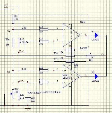
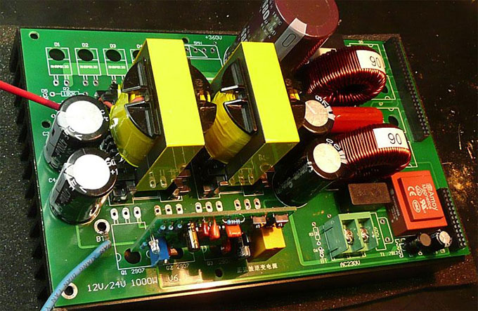 This power inverter is designed for 12v DC, but also can be connected to 24v DC, my goal is 800 watt, strive to 1000 watt pure ...
This power inverter is designed for 12v DC, but also can be connected to 24v DC, my goal is 800 watt, strive to 1000 watt pure ...